Flowserve QLQ Vertical Worthington User Manual
Page 48
QLQ, QLQC USER INSTRUCTIONS ENGLISH 87900027 – 06/14
Page 48 of 61
Cast Iron /
Bronze
12% Cr Steel
316 SS steel
Carbon steel
in in In
3 ÷ 3.49
0.0141
0.0193
3.5 ÷ 4.99
0.0157
0.0209
5 ÷ 5.99
0.0169
0.0220
6 ÷ 6.99
0.0181
0.0232
7 ÷ 7.99
0.0189
0.0236
8 ÷ 8.99
0.0197
0.0248
9 ÷ 9.99
0.0209
0.0260
10 ÷ 10.99
0.0220
0.0279
11 ÷ 11.99
0.0232
0.0283
12 ÷ 12.99
0.0240
0.0291
13 ÷ 13.99
0.0252
0.0303
14 ÷ 14.99
0.0260
0.0311
15 ÷ 15.99
0.0272
0.0323
16 ÷ 16.99
0.0279
0.0331
17 ÷ 17.99
0.0291
0.0342
18 ÷ 18.99
0.0299
0.0350
6.8.2 Maintenance of shaft./s and shaft sleeves
When the pump is dismantled, all shafting should be
examined carefully for corrosion, wear and distortion.
The impeller hub fit on the lower shaft should be
checked for rusting or pitting. All keyways should be
checked for tight key fit since a loose fit subjects the
shafting to shock loading.
Replace a shaft that is bent or distorted. If the shaft
shows wear at the impeller hub or a sleeve location, it
may be possible to rebuilt it by metal spraying or
plating and regrinding. This repair should only be
carried out by trained and competent personnel. After
a shaft has been repaired, check it for possible run-
out. Recheck it after complete assembly of the rotor.
All shaft sleeves should be checked for wear prior to
reassemble of the pump. Any sleeve indicating wear
should be replaced.
Shaft sleeve on intermediate shafting are shrunk in
position to match the bearing bushings.
Remove worn sleeves by mechanical turning.
To fit new sleeves, place sleeves in an industrial oven
and heat at 120°C (250°F).Slide the heated sleeves
onto the shaft in position.
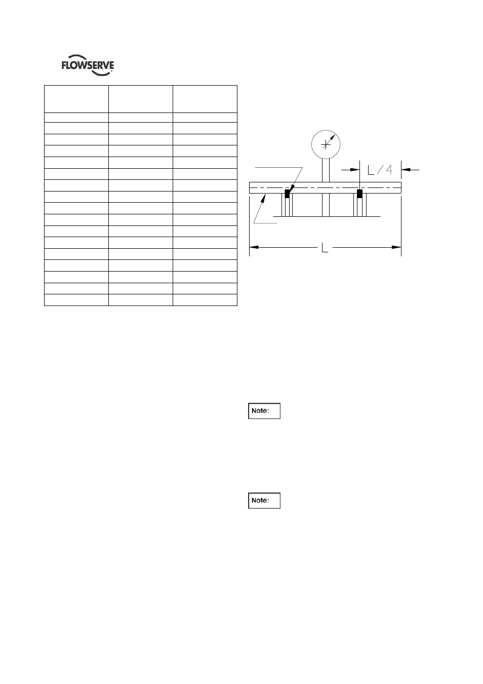
Check the shafts for straightness, pitting and wear.
Remove all burrs or nicks. Shaft damage is usually
best corrected by replacing the shaft.
The detail below shows the recommended method for
checking shaft straightness.
6.8.3 Maintenance of shaft guide bushings
Check all bearings for total clearance over the shaft.
It is recommended that all bearings indicating visual
wear be replaced. In addition, any bearings whose
running clearance exceeds "As New" tolerances by
more than 50% should be replaced.
"As new " diametrical clearance are 0.2 ÷ 0.3 mm
(0.008÷0.012 in).
Worn bearings can cause pump vibration and can
result in damage to the wearing rings and mechanical
seal.
Bearing bushings are pressed in their seats. Remove
worn bushings by mechanical turning. To fit the new
bushings use a suitable press.
Rubber bearings should always be replaced
when servicing a pump.
6.8.4 Maintenance of thrust bearing (if provided)
Anti- friction bearings are shrunk on the shaft guide
sleeve. A pulling device must be used to remove
them. The pulling jaws or fingers must be located
behind the shoulder of the inner race.
Unless extreme care is used when
removing an anti-friction bearing, the bearing may be
damaged and therefore no longer usable.
Check always the bearing immediately after removal
for any imperfections or any play between the races.
It is recommended that new bearings are used for
replacement of removed bearings since it happens
very often that the damages caused by removal
cannot be detected until the pump is put into
operation.
ROLLERS
DIAL INDICATOR
SHAFT