Flowserve HWX Worthington User Manual
Page 30
HWX USER INSTRUCTIONS ENGLISH - 07/14
Page 30 of 40
•
then by comparing diameter of bore of
impeller with corresponding diameter of shaft.
Diameter of bore of impeller should be 0.013
mm (0.0005 in.) to 0.38 mm (0.0015 in.)
oversize of the corresponding diameter of
shaft.
The diameter of the impeller bore
must never be oversize of its counterpart on shaft
by more than the allowable tolerance. If the
impeller bore is not within tolerance, you should
contact the nearest FLOWSERVE Pump Sales
Office for recommendations concerning your
particular circumstance.
6.8.3 Oil Thrower (if applicable)
In case of Oil Cascade Lubrication, install thrower
onto shaft. Secure thrower to shaft by tightening set
screws into the location groove in the shaft.
6.8.4 Bearings Housing
The ball bearings require correct handling and
installation to ensure optimum performance. The
following information is intended as a minimum to
ensure that the bearings are handled and installed
correctly. As you assemble the pullout element, keep
soft cables or nylon lifting straps and hoist handy for
heavy parts.
If you have not match-marked the casing
cover, the bearing housing, and seal plate to identify
their orientation, you should determine their correction
orientation by studying the OUTLINE drawing before
commencing assembly of the pullout element.
If the intent is to replace only the Mechanical Seal
Part proceed to section 6.8.4.1
1. Make certain that all visual inspection
requirements have been met, including
verification of shaft straightness, wear ring
running clearance, stuffing box bushing running
clearance, and fit between impeller and shaft
(see Section 6.7 “Examination of parts”).
2. Place shaft in a soft-faced vise (that is, a vise with
faces covered with a soft material such as
copper) to prevent marring; then clamp it so that
the radial and thrust bearings can be slipped onto
shaft.
6.8.4.1 Bearings handling
a) Do not remove new bearings from their storage
package except for inspection, when stored for a
long period of time or just prior to their
installation.
b) Work area must be clean to ensure that no dirt or
other contaminates will enter the bearings.
Handle bearings with clean, dry hands and with
clean, lint free rags. Lay bearings on clean paper
and keep covered. Never expose bearings on a
dirty bench or floor.
c) Do not wash a new bearing. It is already clean
and the preservative should not be removed.
d) Before mounting, be sure shaft bearing areas are
clean and free of nicks and burrs. Check the
dimensions of these areas to ensure correct fit of
bearings.
6.8.4.2 Bearing installation
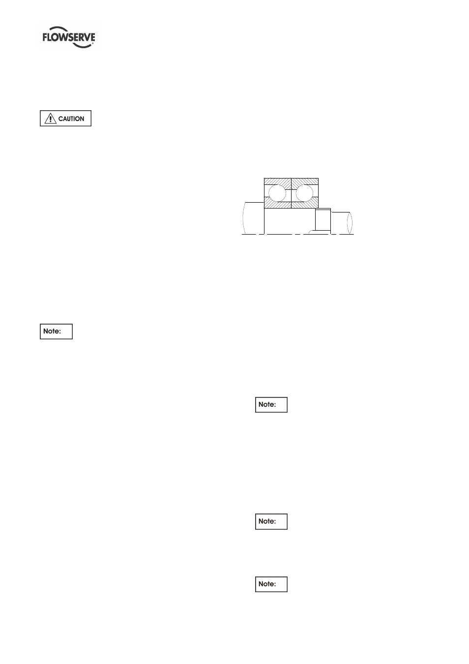
Install the thrust and radial bearings in the same
sequence and direction as removed.
Figure 6.5 - Oil Cascade and Oil Mist Lubrication -
There are two simple methods of providing a heat
source for expanding the inner race of the bearings to
facilitate mounting.
a) In the first method, bearings still wrapped in their
original intimate wrap are placed on a shelf in a
temperature controlled oven, or in an enclosure
lined with foil
and heated with electric light bulbs.
A temperature of 66 °C (150 °F) for one half hour
should be sufficient.
b) A second method consists of locating a light bulb
100 to 150 Watt (0.13 to 0.15 hp) in the bore of
the bearing. The light bulb will heat, primarily, the
inner ring and the bearing can usually be handled
by the outer ring without special gloves. Care
must be taken to keep the bearing clean and
uncontaminated.
The old and once popular method of
heating bearings in an oil bath is DEFINITELY
DISCOURAGED. HEATING INNER RING WITH
A GAS TORCH IS PROHIBITED. In either
case, it is difficult to control the heating rate
and final temperature and even more difficult
to keep the oil and/or bearing clean.
c) When bearings are installed on the shaft make
sure the bearing is installed squarely and is firmly
seated. Hold bearing in place until it has cooled
sufficiently so that it will not move from position.
Cover bearings to protect them from dirt.
When installing the bearings the
mounting pressure should never be applied
in
such a manner that it is transmitted through
the rolling element. Apply the mounting force
directly against, and only against, the inner
ring.
Inner thrust bearing must be
assembled against shoulder on shaft with the