First Co HBC (X) User Manual
Page 3
tions are complete the system must
be pressure tested. Repair any solder
joint leaks and gently tighten any leak-
ing valve packing nuts and piping ac-
cessories as required. Hydronic sys-
tems are not designed to hold pres-
surized air and should only be tested
with water.
PIPING INSULATION
After the system has been proven
leak free, all lines and valve control
packages must be insulated to pre-
vent condensate drippage or insu-
lated as specified on the building
plans.
Note: Many valve packages will not
physically allow all components to fit
over an auxiliary drain pan. It is the
installers responsibility to insulate all
piping to ensure adequate condensa-
tion prevention.
DUCT WORK
All duct work must be installed in
accordance with industry accepted
practices, and all applicable national
and local code requirements.
NOISE
These fan coil units are designed
for quiet operation, however, all air
conditioning equipment will transfer
some amount of noise to the condi-
tioned space. This should be taken
into consideration when planning the
location of the equipment.
MOUNTING
It is important to ensure that the fan
coils are securely mounted and the
structure is sufficient to support the
weight of the equipment. All anchors
for mounting the equipment must be
placed and sized to ensure a safe and
durable installation.
These units are provided with six
(6) mounting holes. Metal washers
and nuts of the proper size are to be
provided by the installer. When nec-
essary use shims to obtain the proper
level. This will ensure that the con-
densate will drain from the unit.
INSTALLATION
PRECAUTIONS
Installation of this equipment
should only be performed by properly
trained personnel to ensure proper
installation and the safety of the in-
staller. The following are some pre-
cautions to be followed for typical in-
stallations.
1. Always use proper tools and equip-
ment.
2. No wiring or other work should be
attempted without first ensuring that
the fan coil is completely discon-
nected from the power source and
locked out. Always verify that a good
ground connection exists prior to en-
ergizing any power sources.
3. Always review the nameplate on
each unit for proper voltage and con-
trol configurations. This information
is determined from the components
2-Way Motorized Valve Assemblies
1. The motorized valve assembly should be attached to
the supply header which is the connection nearest the air
outlet flange on the unit.
2. Prior to soldering the joints, operate all the hand valves
to ensure that the handles will fully open and close without
interference to other valves, ceiling, wall, plenum or other
accessories.
3. All valves will operate at any angle with the exception
of the motorized valve, which must never be installed with
the power head below horizontal. The actuator box
requires a 3/4" clearance for removal.
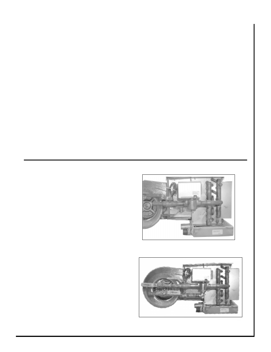
3-Way Motorized Valve Assembly
1. The 3-way valve assemblies will mount to the coil in
only one position. On four-pipe right hand systems a "B"
valve assembly is required for the chilled water connec-
tion and a "A" valve assembly is required for the hot water
connection. On left hand systems a "A" valve assembly is
required for the chilled water connection and the hot water
connection. (See figure1.)
2. Prior to soldering the joints, operate all the hand valves
to ensure that the handles will fully open and close without
interference to other valves, ceiling, wall, plenum or other
accessories.
3. All valves will operate at any angle with the exception
of the motorized valve, which must never be installed with
the power head below horizontal. The actuator box
requires a 3/4" clearance for removal.
Figure 2 - Installation of Valve Cluster Assemblies