Warning, Piping, General piping precautions – First Co SHW (2 - 20 Tons) Horizontal Chilled Water User Manual
Page 2: Wiring diagrams
RED
G
C
BLK
WHT
120V
24V
W
R
Y
BLK
BLK
BLK
GRD
BLOWER
MOTOR
****** WARNING ******
When connecting piping or
valve kits to blower coil units,
do not bend or reposition the
coil header tubing for align-
ment purposes. This could
cause a tubing fracture re-
sulting in a water leak when
water pressure is applied to
the system.
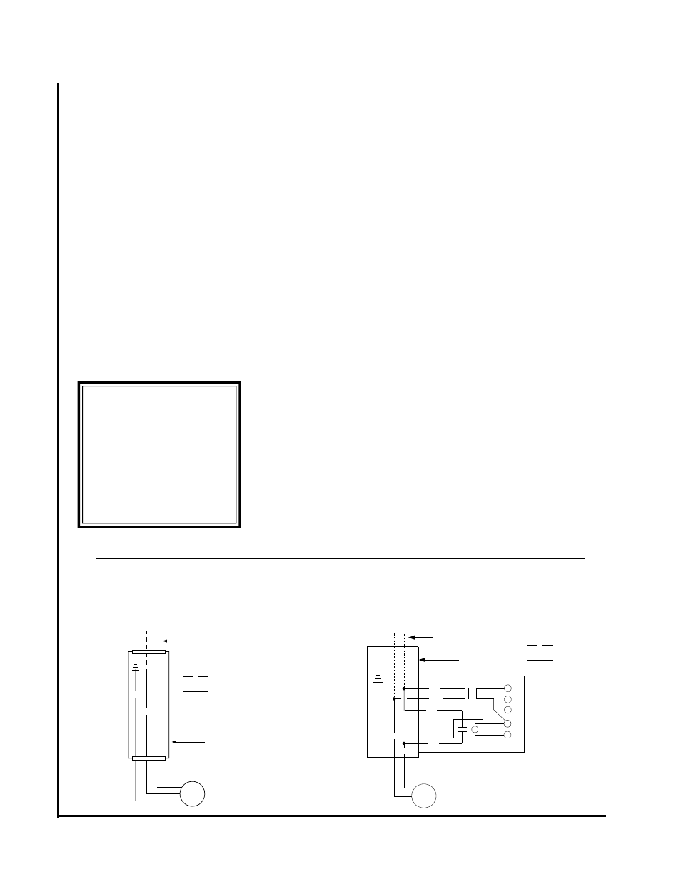
These blower coil units can be
provided with a optional Class 2
relay/transformer for 24-volt control
circuits (3/4 HP maximum load rat-
ing). Should any add-on equipment
also have a Class 2 transformer
furnished, care must be taken to
prevent interconnecting outputs of
the two transformers by using a th-
ermostat with isolating contacts.
PIPING
These units employ a hydronic coil
designed for use with either hot or
chilled water. Each coil has a 1/4
inch bleed line.
All piping must be adequately
sized to meet the design water flow
requirements as specified for the
specific installation. Piping must be
installed in accordance with all ap-
plicable codes. All chilled water
piping must be insulated to prevent
condensation.
The piping connections on the
equipment are not necessarily in-
dicative of the proper supply and
return line sizes. To minimize re-
strictions, piping design should be
kept as simple as possible.
Caution: Prior to connecting to the
blower coil all external piping must
be purged of debris.
Condensate drain lines must be
installed with adequate slope away
from the unit to assure positive
drainage. Since the drain pan is
located on the suction side of the
blower, a negative pressure exists at
the drain pan and a minimum trap of
1-1/2 inches must be provided in the
drain line to assure proper drainage.
NOTE: Drain pan has positive slope
to the nipple which is located on the
coil connection side of the unit.
GENERAL PIPING
PRECAUTIONS
1. Flush all field piping prior to
connection to remove all debris.
2. Use wet cotton rags to cool valve
bodies, if present, when soldering.
3. Open all valves (mid-way for
hand valves, manually open on
motorized valves) prior to soldering.
4. When soldering to bronze or
brass, heat the piping while in the
socket/cup and begin introducing
the solder when the flux boils rap-
idly. Avoid direct flame into the
solder joint.
5. Heat can only be applied to the
cup of the valve body for a minimal
time before damage occurs (even
with the use of wet rags.
6. Avoid rapid quenching of solder
joints as this will produce joints of
inferior quality.
7. The coil header or valve package
will not support the weight of the
connecting pipes. All pipes which
are connected to the unit must be
completely supported prior to con-
nection to the unit.
8. Provisions must be made for
expansion and contraction of piping
systems. All horizontal and vertical
risers, including runouts, must be
able to withstand significant move-
ment with temperature changes.
Failure to do so will result in damage
and failure of piping, fittings and
valves throughout the building.
9. Never insulate the heads or mo-
torized portion of control valves.
Damage can occur in the form of
excessive heat build up and interfer-
ence to the operation and moving
parts may result.
10. All piping fabricated in the field
should be installed with consider-
ation of additional space for any
electrical routing that may be re-
quired.
11. Connect all piping per accepted
industry standards and observe all
regulations governing installation of
piping systems. When all connec-
tions are complete the system must
be pressure tested. Repair any sol-
der joint leaks and gently tighten any
leaking valve packing nuts and pip-
ing accessories as required. Hy-
dronic systems are not designed to
hold pressurized air and should only
be tested with water.
WIRING DIAGRAMS
STANDARD UNIT
OPTIONAL RELAY / TRANSFORMER
(FIELD INSTALLED)
N L
FIELD WIRING
FACTORY WIRING
FAN
MOTOR
GRD
BLK
BLK
120V-1PH-60HZ
SUPPLY
JUNCTION
BOX
FIELD WIRING
FACTORY WIRING
120V-1PH-60HZ
SUPPLY
JUNCTION
BOX
RELAY / TRANSFORMER
3/4 HP Max. Load Rating
N L