Maintenance, Condensate drain line, System start-up – First Co VCB User Manual
Page 4: Thermostat / control wiring, Electrical
MAINTENANCE
1) The filters must be cleaned to maintain optimum perfor-
mance. They should be inspected and cleaned once a
month if required. The filter is a permanent type and may
be removed and washed with a garden hose. Filter should
be completely dry before reinstalling. To remove the filter,
rotate the retaining rod holding the front edge of the filter so
it can drop below the front panel of the cabinet then pull
outward to remove. To reinstall the filter, slide the filter into
the filter channels on both sides of the unit. Rotate filter
retaining rod, on lower front edge of cabinet door, so that it
is under the filter then push the rod upward into the cabinet
door.
2) The condensate drain pan can pick up lint and dirt, espe-
cially with dirty filters. Inspect the drain pan twice a year to
avoid the possibility of overflow.
3) The coil must be clean to obtain maximum performance.
Check once a year under normal operating conditions and,
if dirty, brush or vacuum clean. Care must be taken not to
damage the aluminum fins while cleaning.
CAUTION: Fin edges are sharp and a potential injury
hazard.
4) If motor service is required, it can be removed in the
following manner:
a) disconnect electrical power to the unit at the discon-
nect switch and lock out.
b) remove two screws, securing blower deck to unit.
c) locate motor lead wires where they connect to the
side panel, (lower rear on the electrical box side).
d) the quick connect plug needs to be squeezed on top
and bottom to release it from its socket. (Dual motor
units have two plugs)
e) now slide blower / motor deck out of unit to service.
f) reverse process to install.
5) On units equipped with back fresh air intake, the insect
screen may be removed for cleaning by lifting the intake box
slightly and pulling it out.
CONDENSATE DRAIN LINE
Drain line installation must adhere to all code requirements.
The plastic drain pan is to be located under the coil / valve
connections supported by its mounting bracket. Make sure
drain pan is level for proper drainage.
The drain pan connection is suitable to receive a standard
3/4" PVC coupling or elbow. Route the condensate line such
that it will have adequate slope from the pan to the drain. After
condensate line has been run, make sure plastic drain line from
blower plate nipple is routed to plastic drain pan and plastic cap
is installed on other nipple on the blower plate.
Note: All chilled water piping not located over the drain pan
must be insulated by the installing contractor to prevent
condensation damage.
SYSTEM START-UP
1) Prior to start-up, inspect the blower to assure the wheels
turn freely without rubbing on the housing.
2) Pressurize water coil by opening water valves and bleeding
the air from the coil and system.
3) Check 2-way or 3-way valves for proper operation by
energizing thermostat accordingly.
4) Check that blower motor operates on all three speeds.
5) Replace unit cover panel by interlocking top / back edge
with cabinet frame. Watch to see that unit mounted thermo-
stat protrudes through the cutout of the cover panel. Align
ball pin on each side with cabinet frame and push firmly to
engage and lock.
6) Check to make sure filter is installed correctly within the
filter channels on each side. Rotate filter retaining rod, on
lower front edge of cabinet door, so that it is under the filter
then push the rod upward into the cabinet door.
THERMOSTAT / CONTROL WIRING
UNIT MOUNTED THERMOSTAT
A line voltage thermostat is factory mounted and wired. Once
power is applied to the unit, it is ready to operate. All standard
thermostats have continuous fan if system switch is on.
REMOTE OR WALL MOUNTED THERMOSTAT
If a remote or wall mounted thermostat is used, all wiring is field
supplied and must meet local and national code requirements.
Refer to unit wiring diagram for proper connections.
-4-
ELECTRICAL
All wiring must comply with local and national code require-
ments. The customer or contractor is to provide branch circuit
overcurrent protection and disconnect means. Units are pro-
vided with wiring diagrams located on the blower housing, and
nameplate data to provide information required for necessary
field wiring.
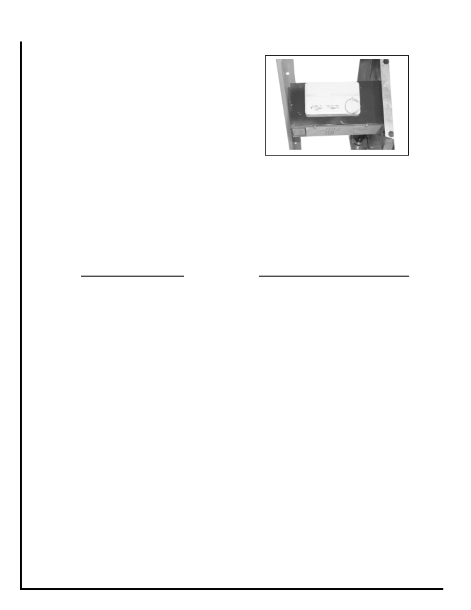
Bring the field electrical wiring into the back of the end
compartment opposite the coil connections to the control box.
(Figure 7, Unit mounted controls shown) There is a 7/8" hole
in the control box bottom. Connect power supply in accordance
to wiring diagram.
Figure 7