Auxillary float switch installation, Brushless dc motor connections – First Co UC - Vertical front return with electric heat User Manual
Page 4
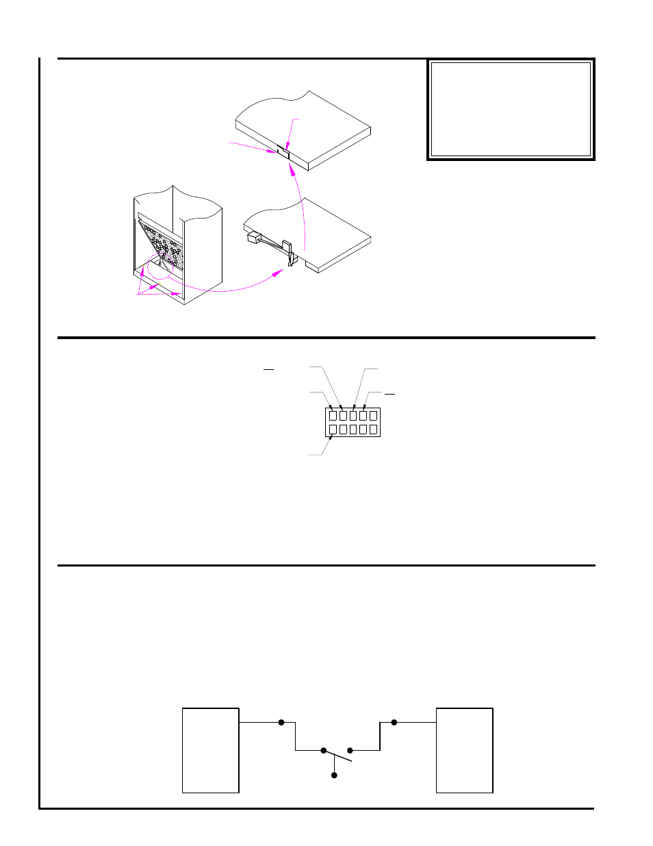
AUXILLARY FLOAT
SWITCH INSTALLATION
Figure 4
BEND HERE
REMOVE / REPLACE
3 SCREWS
ALLIGATOR CLIP
DRAIN FITTING
COVER
POSITION SWITCH
BEHIND STEP
Auxillary Float Switch
Drain pan overflow protection switches may be attached to the drain fitting cover using the following technique illustrated above.
See figure 4.
1) Remove drain fitting cover, 3 screws.
2) Using pliers, bend flange out at its attachment point.
3) Reinstall cover.
4) Clip switch assembly behind the step on the flange, alligator clip.
5) Route a red low voltage wire from junction box red pig tail to switch.
6) Add another red 18 gauge or larger lead back from the switch onward to the thermostat as done normally.
FLOAT SWITCH
FAN
COIL
RED
LOW
VOLTS
T-STAT
RED
**MAINTENANCE UPDATES**
For a current copy of the
Maintenance Program log on
to www.firstco.com and
look under "Product Informa-
tion"
BRUSHLESS DC MOTOR CONNECTIONS
IF SO EQUIPPED
SEE WIRING DIAGRAM
Figure 5
C L G N
1 2 3 4 5
24VAC
Common
208
240
VAC L2
Chassis Ground
208
240
VAC L1
Five Available Programmed
Speed taps, 24VAC, See
Wiring Diagram on Unit