Warning, Operation and maintenance – First Co HBQB (High Efficiency) User Manual
Page 3
the circulating loop to permit servicing
of the system if required and to assist
in purging the system.
NOTE: Hot water coil freeze protec-
tion is available for applications
where the fan coil is located in ambi-
ent air locations (attics, crawl
spaces, etc.) or within structures that
may be unoccupied during freezing
conditions. Consult the factory for
additional information.
OPERATION AND
MAINTENANCE
Pre-start Check
• Check that supply voltage matches
nameplate data.
• Ensure that the unit is properly
grounded.
• With power off, check blower wheel
set screw for tightness and ensure
that the blower wheel rotates freely
and quietly. Remove the motor
blower shipping brace on the
60HBQB or MBQB blower assembly.
•
Check that the water coil, valves
and piping have been leak checked
and insulated as required.
•
Ensure that all air has been vented
from the hot water coil.
NOTE: It may require purging several
gallons of water so have a means of
discarding the water.
•
Install all panels.
NOTE: The blower door must be in
place for the unit to operate due to the
door safety switch.
****** WARNING ******
• Always wear eye protection.
• When fan coil is operating,
some components are operating
at high speeds. Personal injury
can result from touching these
items with any object
• All electrical and service
access panels must be returned
and secured in their proper
place.
• Clear surrounding area of all
tools, equipment and debris.
• Check the entire unit to
ensure it's cleanliness.
****** WARNING ******
The manufacturer does NOT
WARRANT equipment sub-
jected to abuse. Metal chips,
dust, drywall tape, paint over
spray, etc. can void warranties
and liability for equipment
failure, personal injury and
property damage.
•
Install any filters which may have
been removed during the installation
process.
****** WARNING ******
To prevent pump damage,
the fan coil unit should not be
energized for heating until the
hot water coil and all water
lines have been purged of air.
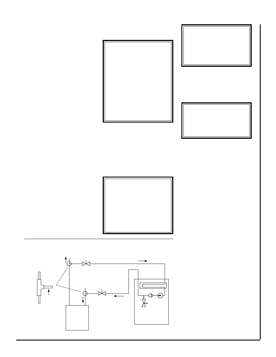
TYPICAL PIPING SCHEMATIC
Figure 1
****** WARNING ******
Hot water can cause scalding.
A hot water mixing valve can
be applied to the system to
temper domestic water draw.
Start-up
Before start-up all of the compo-
nents should be given a thorough
check. Optimal operation of this
equipment requires cleanliness. Of-
ten after installation of this equipment
additional construction activities oc-
cur. Care must be taken to protect
the equipment from debris during
these construction phases.
Heating Cycle Start-up
1) Fill the water heater. Open a hot
water faucet while filling the water
heater to vent the air. When the tank
is full and all the air is purged, close
the faucet.
2) Ignite the water heater and set the
thermostat to 140 degrees.
3) Purge the air handler’s hot water
coil and lines.
NOTE: It may require purging
several gallons of water so have a
means of discarding the water.
Close valve number 1 and open valve
number 2. (See figure 1) Next, open
the air bleed valve. When all of the air
is purged from the lines close valve
number 2 and open valve number 1.
After all the air is purged from the coil
and lines, open both valve number 1
and 2 and close the air bleed valve.
4) Switch the room thermostat to the
"Heat" position and raise the tem-
perature setting to a position approxi-
mately ten degrees above room tem-
perature.
NOTE: The door switch must be
activated to operate the unit.
NOTE: The heating cycle has a
time delay relay to delay the blower
on a call for heat.
The pump should energize and begin
circulating the hot water through the
coil. If the pump is operating properly
and the water temperature in the wa-
ter heater has reached the set point,
then the hot water inlet at the fan coil
unit will be hot. If the pump is running
but hot water is not circulating, open
HOT WATER COIL
1
2
TEE FITTINGS
MUST BE
INSTALLED AS
SHOWN. REFER TO
INSTRUCTIONS
FOR DETAILS
HOT WATER
SUPPLY TO
HOUSE
TO
HEATING
LOOP
FAN COIL UNIT
AIR
BLEED
VALVE
HOT
WATER
HEATER
CHECK
VALVE
PUMP
FLOW
FLOW
WATER SUPPLY
TO HOT WATER
HEATER
1) ISOLATION VALVE: SUPPLY
2) ISOLATION VALVE: RETURN
Y LINE (FIELD SUPPLIED)
N LINE (FIELD SUPPLIED)