Typical piping schematic, Pump replacement, Check valve replacement – First Co FWA-HW User Manual
Page 4
4) Switch the room thermostat to the
"Heat" position and raise the tem-
perature setting to a position ap-
proximately ten degrees above
room temperature.
NOTE: The door switch must be
activated to operate the unit.
The pump should energize and be-
gin circulating the hot water
through the coil. If the pump is
operating properly and the water
temperature in the water heater has
reached the set point, then the hot
water inlet at the fan coil unit will be
hot. If the pump is running but hot
water is not circulating, open the air
bleed valve long enough to purge
any remaining air from the hot water
lines and coil. This will allow the
pump to begin circulating hot wa-
ter.
5) The water heater thermostat should
be adjusted so that the water tem-
perature entering the hot water coil
is as close to 140 degrees as pos-
sible with the system energized
and operating long enough for all
temperatures to stabilize.
PUMP REPLACEMENT
Disconnect electrical power before
servicing the unit.
To replace the circulator pump,
close the isolation valves and relieve
the water pressure within the heating
loop. Disconnect the pump's 115 volt
power lines within the control box and
remove the four hex head screws se-
curing the pump motor to the pump's
volute.
Reverse the above steps for reas-
sembling the pump, however make
sure that the pump or volute has the
rubber o-ring in place before assem-
bling.
CHECK VALVE
REPLACEMENT
Disconnect electrical power before
servicing the unit.
To replace the internal check valve,
close the isolation valves and relieve
the water pressure within the heating
loop. Remove the four hex head
screws securing the pump motor to
the pump's volute and remove. The
check valve is located in the volute.
Rotate the check valve to release and
remove from the volute.
Reverse the above steps for rein-
stalling a check valve, however make
sure that the pump or volute has the
rubber o-ring in place before assem-
bling.
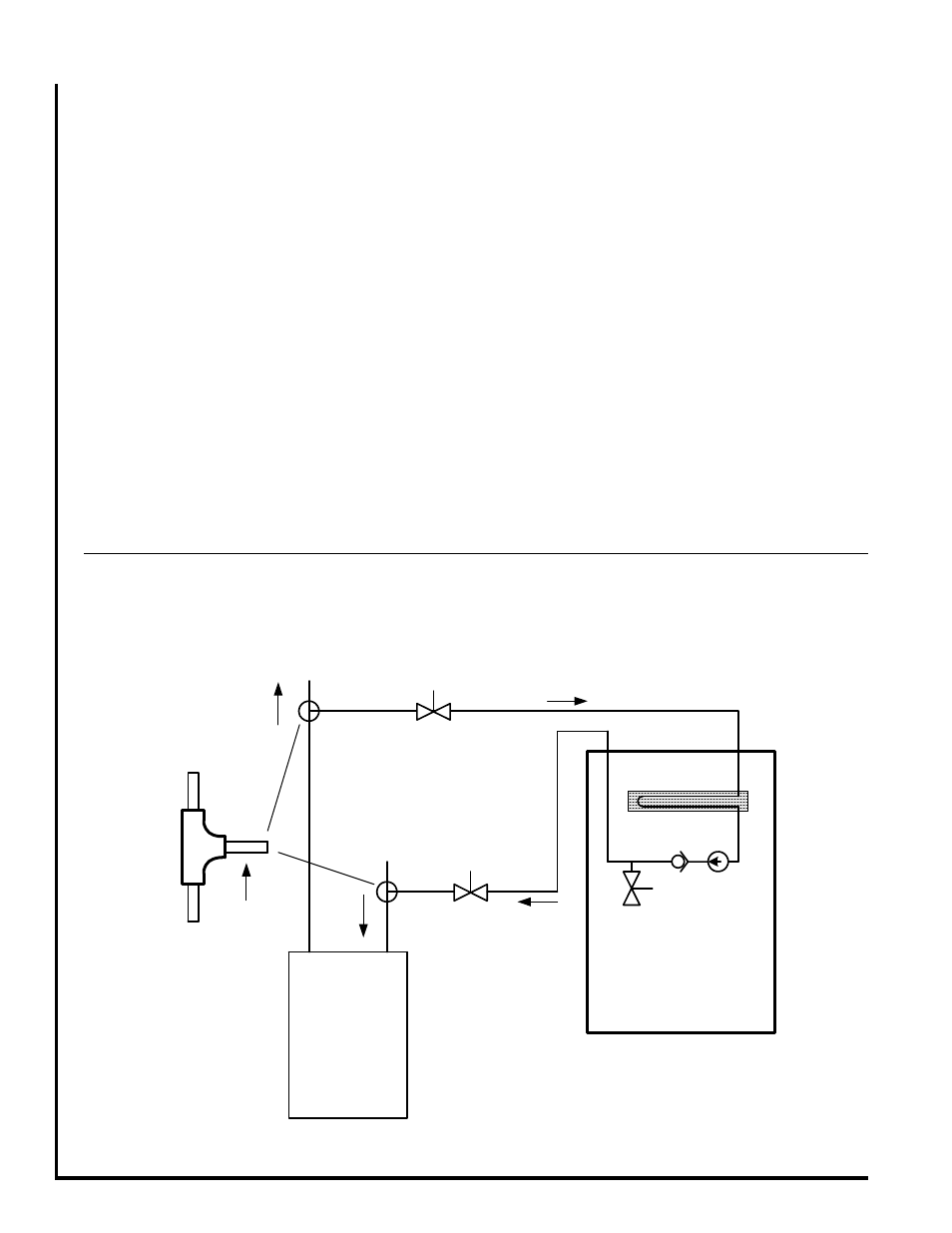
TYPICAL PIPING SCHEMATIC
Figure 1
FLOW
FLOW
1) ISOLATION VALVE: SUPPLY LINE (FIELD SUPPLIED)
2) ISOLATION VALVE: RETURN LINE (FIELD SUPPLEID)
HOT WATER COIL
AIR
BLEED
VALVE
HOT
WATER
HEATER
WATER SUPPLY
TO HOT WATER
HEATER
HOT WATER
SUPPLY TO
HOUSE
1
2
TO
HEATING
LOOP
TEE FITTING MUST
BE INSTALLED AS
SHOWN. REFER TO
INSTRUCTIONS FOR
DETAILS
FAN COIL UNIT
CHECK
VALVE
PUMP