First Co WCX12 Replacement Units User Manual
Page 2
WARNING: Before installing or servicing unit, always turn off all power to unit. There may be more than one disconnect
switch. Electrical shock can cause personal injury or death.
INSTALLATION PRECAUTIONS
Installation of this equipment should only be performed by properly trained personnel to ensure proper installation and the safety of
the installer.
Compressor start assist devices (capacitor and start potential relay) may be required for installations with long line length, unusually
high or low ambient operating conditions, thermostatic expansion valves or any other situation which can lead to slow off cycle pres-
sure equalization and excessive compressor starting problems.
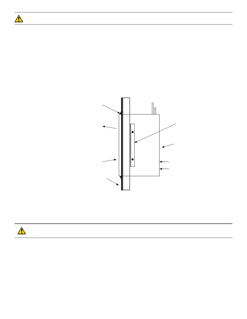
UNIT LOCATION
This unit is intended to be used in a thru-the-wall application with the coil surface side of the unit exposed to the outside of the
structure and the unit access panel exposed inside the structure. A wall opening of suffi cient size to allow sliding the unit through
must be provided with framework suffi cient to support the unit to the wall. The unit cabinet must not be relied on to provide wall
support. Mounting angles are provided for use in attaching the unit cabinet to the framework on the inside surface of the opening. In
attaching the angles to the unit cabinet take care that no screws are driven into the refrigerant tubing inside the cabinet. The opening
around the unit must be caulked and sealed to prevent rain leakage. Use silicone sealant or other high grade non hardening sealing
compound approved for exterior use. (See fi gure 1)
Care must be taken not to block the drain holes provided at the bottom of the unit. These holes allow for drainage of any rain that
may be blown into the unit.
CAUTION: If a reduction of air fl ow or a recirculation of air fl ow occurs the unit performance will decrease. This
condition will cause premature equipment failure and void all warranties.
For the unit to function properly, there must be no restriction to free circulation of the condenser air. If architectural design consid-
erations make it necessary to locate the unit behind a decorative grille the unit performance will be reduced if a reduction of air fl ow
or a recirculation of air fl ow occurs. It may be necessary to provide a baffl e between the face of the unit and the decorative grille to
prevent recirculation of the hot discharge air back into the coil face. The added grille must be as open as possible to achieve the best
performance.
If more than one WCX12 unit is to be installed in the same area a minimum of 36”spacing on the vertical and 18" on the horizontal
is recommended between units to minimize recirculation of condenser exhausted air.
For units that are to be installed in the interior of a building or in return air spaces care should be taken to seal any openings in the
cabinet that would allow hot condensing unit air into the conditioned space. Failure to seal these openings may result in erratic system
operation and in driving rain situations may allow water infi ltration into the structure.
In cold climate areas, units installed in interior and return air spaces may require that insulation be added to the exterior of the
WCX12 cabinet to reduce heat loss thru the cabinet and possible condensation on the cabinet surfaces which could result in water
damage.
CAULK WATER TIGHT
AIR OUT
AIR IN
EXTERIOR BUILDING
SURFACE
ELECTRICAL SUPPLY
T’STAT WIRING
SERVICE ACCESS PANEL
MOUNTING ANGLES (2)
(SUPPLIED WITH UNIT
FIELD INSTALLED)
REFRIGERANT PIPING
(FIELD SUPPLIED)
INSIDE
OUTSIDE
TYPICAL INSTALLATION
(SIDE VIEW)
FIGURE 1
Note: WCX12 cabinet should protrude
thru wall beyond the fi nished outside
surface by 1/4 to 1/2 inch.