Operation and start-up, Warning – First Co CDXQ Uncased with pump (HW) User Manual
Page 3
vent freezing when piping is run in an
unconditioned space.
NOTE:
The CDXQ fan coil unit comes with
a hot water coil freeze protector. This
device may not sufficiently protect
the water lines if the fan coil is located
in ambient air locations (attics, crawl
spaces, etc.) or within structures that
may be unoccupied during freezing
conditions. Consult the factory for
additional information.
Solder Connections - All copper
joints in the water lines must be made
with low temperature - non lead
solder.
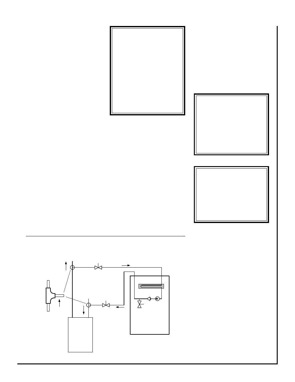
“T” Connections (at the water
heater)- Water lines to and from the
fan coil unit must be taken from the
horizontal connection of the “T” fit-
tings in the vertical hot and cold water
supply lines at the water heater. This
ensures that any air in the system will
be purged each time water is used in
the dwelling. (See figure 1)
Isolation Valves - Two valves are
recommended to be installed within
the circulating loop to permit servicing
of the system if required and to assist
in purging the system.
OPERATION AND
START-UP
Pre-start Check
•
Check that supply voltage matches
nameplate data.
been removed during the installation
process.
Start-up
Before start-up all of the compo-
nents should be given a thorough
check. Optimal operation of this
equipment requires cleanliness. Of-
ten after installation of this equipment
additional construction activities oc-
cur. Care must be taken to protect
the equipment from debris during
****** WARNING ******
• Always wear eye protection.
• When fan coil is operating,
some components are operating
at high speeds. Personal injury
can result from touching these
items with any object
• All electrical and service
access panels must be returned
and secured in their proper
place.
• Clear surrounding area of all
tools, equipment and debris.
• Check the entire unit to
ensure it's cleanliness.
****** WARNING ******
The manufacturer does NOT
WARRANT equipment sub-
jected to abuse. Metal chips,
dust, drywall tape, paint over
spray, etc. can void warranties
and liability for equipment
failure, personal injury and
property damage.
•
Ensure that the unit is properly
grounded.
•
With power off, check blower wheel
set screws for tightness and ensure
that the blower wheels rotate freely
and quietly.
•
Check that the water coil, valves
and piping have been leak checked
and insulated as required.
•
Ensure that all air has been vented
from the hot water loop.
NOTE:
It may require purging several gal-
lons of water so have a means of
discarding the water.
•
Install any filters which may have
****** WARNING ******
To prevent pump damage, the
fan coil unit should not be
energized for heating until
both isolation valves have
been opened and the hot wa-
ter coil and all water lines have
been purged of air.
TYPICAL PIPING SCHEMATIC
Figure 1
these construction phases.
Heating Cycle Start-up
1) Fill the water heater. Open a hot
water faucet while filling the water
heater to vent the air. When the tank
is full and all the air is purged, close
the faucet.
2) Ignite the water heater and set the
thermostat to 140 degrees.
3) Purge the air handler’s hot water
coil and lines.
NOTE: It may require purging
several gallons of water so
have a means of discarding
the water.
Close valve number 1 and open valve
number 2. (See figure 1) Next, open
the air bleed valve. When all of the air
is purged from the lines close valve
number 2 and open valve number 1.
After all the air is purged from the coil
FLOW
FLOW
1) ISOLATION VALVE: SUPPLY LINE (FIELD SUPPLIED)
2) ISOLATION VALVE: RETURN LINE (FIELD SUPPLEID)
HOT WATER COIL
AIR
BLEED
VALVE
HOT
WATER
HEATER
WATER SUPPLY
TO HOT WATER
HEATER
HOT WATER
SUPPLY TO
HOUSE
1
2
TO
HEATING
LOOP
TEE FITTING MUST
BE INSTALLED AS
SHOWN. REFER TO
INSTRUCTIONS FOR
DETAILS
FAN COIL UNIT
CHECK
VALVE
PUMP