Checking/converting the burner orifices – Fire Magic Regal I 34 series Drop In User Manual
Page 16
16
Important:
Test the electrodes for spark before securing
the face to the frame (see also the section
REPLACING THE IGNITOR BATTERY).
9. Replace the face on the frame so the front lip of the face
covers the lip on the frame. Re-secure the face with the
face fastener screws.
10. Replace the control knobs.
11. Replace the fl avor grids and then the cooking grids so that
the cutout section of the grid is in front.
Important
The oven and backburner (where fi tted) are
pre-installed at the factory and should not be
removed from the barbecue during installation.
B AC K B U R N E R O R I F I C E S I Z E C H E C K I N G /
CONVERSION
Before beginning, make sure you have the proper tools for
the task.
This task requires:
•
a #2 Phillips-head screwdriver
•
a #2 fl at-head screwdriver
• a
3/8" wrench or socket screwdriver
Note: It may be necessary to remove the rotisserie rod
before beginning this procedure.
1. Remove the warming rack, if installed, and set it aside.
2. Remove the backburner cover, if installed.
3. Unscrew both backburner face plate screws using a
Phillips-head screwdriver and set them aside.
4. Remove the backburner face plate by pulling the bottom
toward the front of the barbecue and rotating it upward
and outward until the two top tabs can be removed from
the back wall of the barbecue. Set it aside.
5. Remove the backburner assembly anchoring screw on
the lower left of the backburner using a Phillips-head
screwdriver and set it aside.
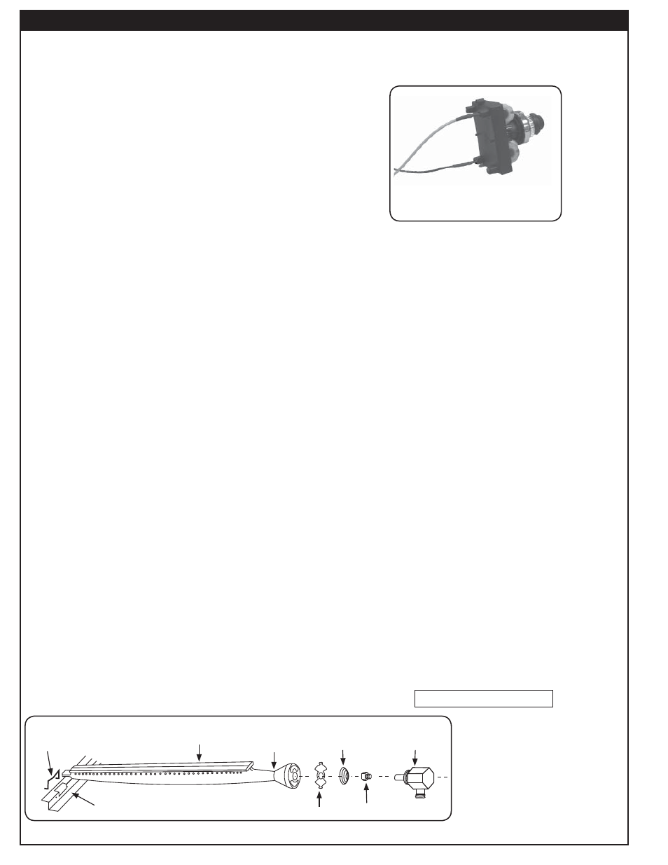
CHECKING/CONVERTING THE BURNER ORIFICES
Fig.
16-2
Spark generator
CHECK FUEL ORIFICES FOR PROPER SIZE
1. Your Regal I barbecue is equipped with fuel orifi ces
for natural gas, unless otherwise indicated. To use
with propane gas, you must install smaller orifi ces to
avoid hazardous overheating. Refer to the MODEL
SPECIFICATIONS TABLE for the proper orifi ce size
needed.
2. Remove the cooking grids and fl avor grids from your
barbecue.
3. If the gas supply has been connected, make sure the
burner valves are in the OFF position. Then carefully pull
the valve knobs from their stems.
Note: Carefully, but fi rmly, lift the top panel away from the
frame. The spark generator for the ignition system
is attached to the top panel. The igniter need not
be detached, but the wires must be unplugged
from the generator before the panel is removed.
4. Using a fl at blade screwdriver, pry the burner retaining
clip from rear wall of the barbecue frame (see
Fig.16-1
).
Remove the burner by; A) Pulling it to the front of the
barbecue; B) Lift the far end out of the notch; C) Pull the
burner away from the manifold, taking care not to lose
the air shutter and spring, which may become detached
when the burner is removed.
5. Using 3/8" socket, remove the orifi ce from the orifi ce
holder on the burner manifold and check the number
stamped on the face. Repeat for each burner as
necessary.
Note: If you have the optional backburner, check the
backburner orifi ce for size.
Note: The air shutter must be re-adjusted after removing
the burner to ensure proper combustion (see the
AIR SHUTTER ADJUSTMENT section).
6. Install the air shutter spring and the air shutter over the
orifi ce holder fi tting in the order and position shown in
Fig.
16-1
. Carefully place the burner(s) back in position,
resting on the back fl ange of the inner liner so that the
brass orifi ce and orifi ce holder fi ttings project well into
the burners.
7. Replace all the burner hold down clips.
8. If you removed the top plate re-install the ignition wires.
Your barbecue may have either two (2) or four (4) wires
depending on the exact model. Pull the drip tray out. Lean
the face forward and plug the wires into the terminals on
the spark generator (Fig.
16-2
). The wires can be plugged
into any terminal.
Fig. 16-1
- Burner orifi ce diagram
Burner
Burner neck
Spring
Burner manifold
Orifi ce
Inner liner
Air shutter
Hold down clip
Continued on next page