EM Acoustics MSE-156 passive fullrange loudspeaker User Manual
Page 9
9
MSE-159/MSE-156 User Manual
www.emacoustics.co.uk
Safety Considerations
When utilising any suspension method, a secondary safety must be used. For any suspension method, fit an M8
eyebolt to any of the rigging points. A safety steel can then be attached to this and connected to your safety
point. If you are in any doubt whatsoever about how to safely suspend your loudspeakers, do not
hesitate to contact your EM Acoustics representative who will be able to refer you to a qualified
rigging company for advice.
Attachment of the FC-159v vertical flying cradle
The FC-159v vertical flying cradle is intended particularly for touring
purposes, hence the extremely quick attachment method.
To attach the cradle, first release the two ball-lock pins from the coffin
plate on the cradle. Position the cradle over the top or bottom of the
loudspeaker (it can be flown either way up) and insert the bosses on
the bottom of the cradle’s coffin-shaped plate into the keyholes on the
enclosure’s flying plate. Slide the cradle to the rear of the enclosure
until the two ¼” diameter locking-pin holes line up. Insert the two
ball-lock pins into the holes to lock the cradle in place. IMPORTANT:
DO NOT ATTEMPT TO LIFT THE LOUDSPEAKER WITHOUT
BOTH BALL-LOCK PINS IN PLACE. The point on the top of the
flying cradle can be used for permanent installations or to secure a
hook clamp. Ensure that an eyebolt is secured to the rear point on
the MSE-159/MSE-156 (M8 at the rear) or one of the top points (M10 on top or bottom) to use as a secondary
safety. To set the angle of the loudspeaker, there are standard clamping levers on each side as a primary system
however as a secondary, and to act as a repeatable method for flying, the holes and ball-lock pins allow quick and
easy angle setting in 5-degree increments.
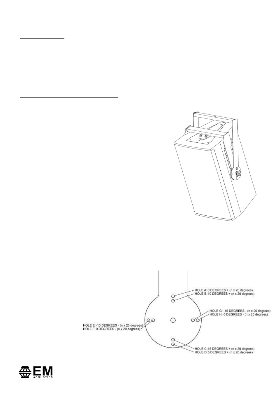
As shown in the diagram
opposite, as you rotate the
inner yoke different holes
will be available to secure
with the pins. Select the
desired angle, and lock in
place with the attached ball-
lock pin. To give further
explanation, Holes A-D are
used for down-tilt and holes