Drake VMM860AG Agile Modulator User Manual
Page 3
Visual Carrier
Frequency (MHz)
471.25
477.25
483.24
489.25
495.25
501.25
507.25
513.25
519.25
525.25
531.25
537.25
543.25
549.25
555.25
561.25
567.25
573.25
579.25
585.25
591.25
597.25
603.25
609.25
615.25
621.25
627.25
633.25
639.25
645.25
651.25
657.25
663.25
669.25
675.25
681.25
687.25
693.25
699.25
705.25
711.25
717.25
723.25
729.25
735.25
741.25
747.25
753.25
759.25
765.25
771.25
777.25
783.25
789.25
795.25
801.25
14
15
16
17
18
19
20
21
22
23
24
25
26
27
28
29
30
31
32
33
34
35
36
37
38
39
40
41
42
43
44
45
46
47
48
49
50
51
52
53
54
55
56
57
58
59
60
61
62
63
64
65
66
67
68
69
UHF BROADCAST CHANNELS
UHF BROADCAST CHANNELS
UHF BROADCAST CHANNELS
UHF BROADCAST CHANNELS
UHF BROADCAST CHANNELS
Channel Number
55.25
61.25
67.25
77.25
83.25
175.25
181.25
187.25
193.25
199.25
205.25
211.25
2
3
4
5
6
7
8
9
10
11
12
13
Visual Carrier
Frequency (MHz)
VHF BROADCAST CHANNELS
VHF BROADCAST CHANNELS
VHF BROADCAST CHANNELS
VHF BROADCAST CHANNELS
VHF BROADCAST CHANNELS
Channel Number
TABLE 2: BC TV
CATV
+100
CATV
BC
TV
CATV
+100
CATV
BC
TV
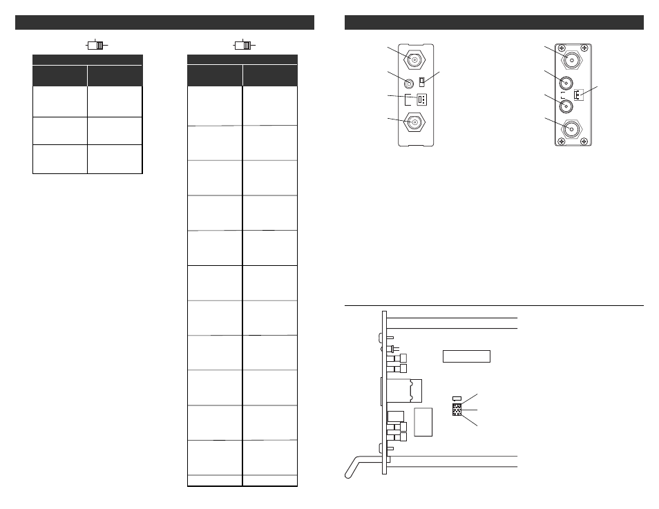
VIDEO INPUT
AUDIO INPUT
DC INPUT
+5V
+12V
GND
RF OUT
FLAT
NORM
R1
R2
R3
R4
Figure 2
Figure 3
R1 - VIDEO INPUT
This is the nominal 1 Vp-p baseband video
input to the modulator.
R2 - LEFT/MONO AUDIO INPUT
This is an unbalanced audio input to the
modulator circuits. This “RCA” (phono)
connector input accepts mono audio in the
case of the VMM860AG or the left channel
audio input in the case of the VMM860AS.
R3 - DC INPUT Connector
This 3-pin connector (Male) accepts the
appropriate mating DC power cable.
R4 - RF OUTPUT
This is the modulator output.
R5 - AUDIO PRE-EMPHASIS SWITCH
VMM860AG only. This switch allows selection
of either normal audio pre-emphasis or flat
audio response. For normal mono audio, set
switch to NORM position. If the MMTS20 BTSC
stereo encoder is used, set this switch to FLAT
and connect stereo audio to the MMTS20. The
encoder will in turn connect to R2.
R6 - RIGHT AUDIO INPUT
VMM860AS only. This is the an unbalanced
input for the right channel stereo audio.
R5
STD Drawing is not to scale. AG and AS
models differ. The correct set of pins
HRC is located directly next to the 45.75
MHz crystal. No jumper installed gives
IRC STD setting.
INTERNAL JUMPER SETTING: STD, HRC, IRC
VIDEO INPUT
AUDIO L
AUDIO R
+ 5 V
+ 1 2 V
G N D
PWR
RF OUT
R1
R2
R6
R4
R3
VMM860AG
VMM860AS
6
BROADCAST TV CHANNEL OUTPUT FREQUENCIES
REAR PANEL CONNECTIONS / INTERNAL JUMPERS 3