Drake VMM600 Fixed Channel Modulator User Manual
Page 2
®
Aural/Visual (A/V) ratios should be held to
-15 dB or less. The output ‘RF’ and ‘A/V
(Ratio)’ controls are used respectively to make
these adjustments.
RACK MOUNTING
Adequate ventilation is very important in
multi-channel installations. Units should be
spaced apart by at least one panel height (1.75”)
wherever possible, and some air movement is
advisable in enclosed rack cabinets.
Excessive heat will shorten component life and
modulator performance will be degraded
without proper cooling.
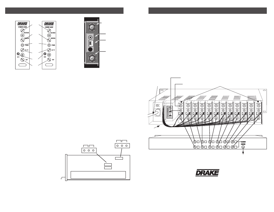
CONNECTIONS AND CONTROLS
All connections to and from each modulator
are made through the rear panel. Figure 3
illustrates an installation with 12 modulator units
combined through a passive signal combiner.
Additional channels can be added by using
additional VMM 600 or VMM 806 modulators
and either multi-port combiners or
combinations of two-port combiners.
INSTALLATION NOTES
Level adjustment provides optimum
performance in multi-channel installations. The
modulator outputs should be checked
periodically with a spectrum analyzer to
maintain a ±1 dB variation of adjacent
channel carriers.
VMM 600's/VMM 806's
AUDIO INPUTS
VIDEO INPUTS
AC POWER
CORD
DC POWER
CABLE
R1 - VIDEO INPUT Connector
This input accepts baseband input thru
4.2 MHz video at levels from 0.7 Vp-p to
1.5 Vp-p.
R2 - AUDIO INPUT Connector
This “RCA” (phono) connector input accepts
baseband audio at a nominal level of 0.5 VPP.
NOTE: two internal jumpers can be configured
to defeat the audio pre-emphasis or stereo
capability. Top cover must be opened to access.
R3 - DC INPUT Connector
This 3-pin connector (Male) accepts the
appropriate mating DC power cable. Observe
proper orientation and wiring.
R4 - RF OUTPUT Connector
This is the modulator RF output
INSTALLATION
3
2 FRONT PANEL DESCRIPTION REAR PANEL DESCRIPTION
R.L. Drake Holdings LLC
710 Pleasant Valley Drive
Springboro
, Ohio 45066
Customer Service and Parts Telephone: +1 (937) 746-6990
Fax: +1 (937) 806-1510
www.rldrake.com
Figure 3
SYSTEM OUT
RF COMBINER
F1 - AUDIO Level Control
This screwdriver adjustment varies the peak
aural carrier deviation. Clockwise rotation
increases the carrier deviation.
F2 - VIDEO Level Control
This screwdriver adjustment varies the video
modulation level. Clockwise rotation
increases the modulation depth.
F3 - POWER Indicator
Lights when the unit is connected to the
required source of DC power via the rear panel
DC INPUT connector.
F4 - A/V Ratio Control
This screwdriver adjustment varies the level of
the aural carrier over a range from 11 to 19 dB
below the visual carrier. The aural carrier
should be adjusted to approximately 15 dB
below the visual carrier (normal operation).
Clockwise rotation increases the aural carrier
level and thus decreases the A/V ratio.
F5 - "CH#" (Channel)
The modulator is factory aligned to the
channel number indicated.
F6 - RF Output Level
This screwdriver adjustment varies the RF
Output level from approximately 35-45 dBmV.
The maximum output level is set with the
adjustment fully clockwise.
F1
F2
F3
F4
F5
F6
2
Figure 1
Figure 2
Internal Jumper Settings
R1
R4
R3
R2
J3
J4
STEREO
MONO
DISABLE
ENABLE
PRE-EMPHASIS