Important safety instructions (conɵ nued), Connections and installation, Setup – Drake DTA-RPS12-DTA Rack W/Supply User Manual
Page 3: Specifications
IMPORTANT SAFETY INSTRUCTIONS (ConƟ nued)
e. If the product has been dropped or damaged in any way, and
f. When the product exhibits a dis nct change in performance—this indicates a need for service.
21. Replacement Parts—When replacement parts are required, be sure the service technician has used replacement parts specifi ed by the manufacturer or have the
same characteris cs as the original part. Unauthorized subs tutes may result in fi re, electric shock or other hazards.
22. Safety Check—Upon comple on of any service or repairs to this product, ask the service technician to perform safety checks to determine that the product is in
proper opera ng condi on.
23. Wall or Ceiling Moun ng—The product should be mounted to a wall or ceiling only as recommended by the manufacturer.
24. Heat—The product should be situated away from heat sources such as radiators, heat registers, stoves, or other products (including amplifi ers) that produce heat.
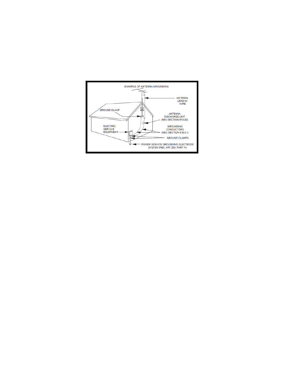
NOTE TO CATV SYSTEM INSTALLERS: THIS REMINDER IS PROVIDED TO CALL THE CATV SYSTEM INSTALLER’S ATTENTION TO ARTICLE 820 - 40
OF THE NEC THAT PROVIDES GUIDELINES FOR PROPER GROUNDING AND, IN PARTICULAR, SPECIFIES THAT THE CABLE GROUND SHALL BE CON-
NECTED TO THE GROUNDING SYSTEM OF THE BUILDING, AS CLOSE TO THE POINT OF CABLE ENTRY AS PRACTICAL.
EXAMPLE OF ANTENNA GROUNDING
CONNECTIONS AND INSTALLATION
1. Using 4 moun ng screws (not included), secure the DTA-RPS12-C CHASSIS to a 19 inch rack. You may wish to install the FRONT PANEL END COVERS while doing
this if you wish to have the ends of the DTA-RPS12-C match the color of the FRONT COVER once the FRONT COVER is installed.
2. Secure the Drake RMM12 Rack Mount Chassis for Mini Mods* to the 19 inch Rack using 4 rack moun ng screws (not included).
3. Insert 12 Drake MPM860AG Channel 3 / 4 Agile Mini Video Processors* into the RMM12. (See STEP 4 under SETUP, as it will be very convenient to make the selec-
Ɵ on menƟ oned in STEP 4 right NOW, as opposed to later once everything is installed.)
4. Insert the Drake PSM121 12-Unit Mini Mod Power Supply* into the RMM12.
5. Insert the 12 Drake MPM860G Channel 3 / 4 Agile Channel Mini Video Processors into the open spots in the RMM12.
6. Connect the PSM121’s power harness cables to each of the MPM860AG’s.
DO NOT CONNECT THE PSM121 INTO A WALL OUTLET NOR ANY OTHER POWER SOURCE YET!!!
7. Secure a 12 Way Spli er* to the 2 threaded posts located on the rear of the DTA-RPS12-C CHASSIS using the two nuts included with the DTA-RPS12-C CHASSIS.
6. Connect the digital cable feed (via coaxial cable) to the input port of the 12 Way Spli er.
7. Connect each of the 12 Way Spli er’s outputs to its own DTA receiver* using coaxial cable.
8. Pair up each DTA with its own Drake MPM860AG Channel 3 / 4 Agile Mini Video Processor, one-to-one, by connec ng the output of each individual DTA to the in-
put on the rear of each MPM860AG using coaxial cable. Ensure that these video connec ons are secure. Make a note of which DTA is paired with which MPM860AG.
9. Insert the 12 DTA receivers into the DTA-RPS12-C CHASSIS.
10. Use the DTA POWER JUMPER CABLES to connect each DTA to the enclosed power source connec ons on the rear of the DTA-RPS12-C.
DO NOT CONNECT THE DTA-RPS12-C POWER CABLE INTO A WALL OUTLET NOR ANY OTHER POWER SOURCE YET!!!
11. Install the DTA-RPS12-C FRONT PANEL over the opening where all of the DTA’s are now stored using the 6 included screws.
12. Connect the output of each MPM860AG with one of the input ports on the DRAKE PC1201 12-Port Passive Combiner (sold separately).
13. Connect the combined output of the PC1201 to the outgoing port exi ng your headend.
14. Install the PC1201 into the 19 inch rack using rack moun ng screws (not included).
15. Once your 19 inch rack with all components installed has been placed securely in a permanent loca on, plug the POWER CORD from the DTA-RPS12-C into a wall
power outlet.
16. Allow a minute or two for the DTA receivers to boot up, and then plug the power cable from the Drake PSM121 into the wall power outlet.
SETUP
1. Set the tuner on each individual DTA Receiver with a remote control unit (should be provided with your DTA receivers).
2. Set the output of each DTA to either Channel 3 or Channel 4 on the standard CATV Channel Plan. Make a note as to what each selected channel/program/sta-
on is being tuned per each individual DTA receiver. Be sure to also note what CATV Output channel you have selected for each DTA. For simplicity, we recommend
se ng all of your DTA’s to output CATV Channel 3 or se ng all of them to output CATV Channel 4. Consult the InstrucƟ on Manual included with the DTA Receivers to
learn how to select a channel from the incoming digital channel plan, and also to ensure that the output of each DTA Receiver is modulated/outpuƫ
ng on either CATV
Channel 3 or Channel 4.
3. Set the input channel on each Drake MPM860AG on its front panel to either Channel 3 or Channel 4, whichever is correct.
4. Set the output channel on each Drake MPM860AG to the desired CATV channel that you wish to have the program modulated to.
5. Make note of all incoming program/channel selec ons, DTA-to-MPM860AG pairings, Channel 3 or 4 selec on per DTA / MPM860AG, and the output CATV Channel
of each MPM860AG.
SPECIFICATIONS
POWER:
100 - 240 VAC ±10%, 60 Hz, 120 W, (per DTA device)
PHYSICAL DIMENSIONS:
19.00” W x 9.00” H x 5.24” D
WEIGHT:
12
lbs
3