6 installation – Drake 300VMF+ Fixed Modulator User Manual
Page 6
6 Installation
CONNECTIONS AND CONTROLS
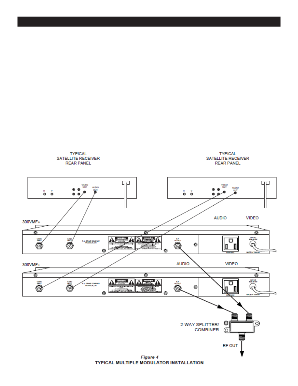
All connections to and from the 300VMF+ are made through
the rear panel. Figure 4 shows a typical two channel
installation using a typical satellite receiver as a signal
source. Additional channels can be added by using
additional 300VMF+ modulators and either multi-port
combiners or combinations of two-port combiners.
INSTALLATION NOTES
Level adjustment provides optimum performance in
multichannel installations. The modulator outputs should be
checked periodically with a spectrum analyzer to maintain a
±1 dB variation of adjacent channel carriers. Aural/Visual
(A/V) ratios should be held to -15 dB or less.
The ‘RF Output Level’ and ‘A/V Ratio’ controls are used
respectively to make these adjustments. If an output level
of less than +43 dBmV is required, add an attenuator of the
appropriate value to the modulator output.
Example:
For an output level of +35 dBmV, add a 12 dB
attenuator pad to the modulator output and set the output
level.
RACK MOUNTING
Adequate ventilation is very important in multichannel
installations. Units should be spaced apart by at least one
panel height wherever possible, and some air movement is
advisable in enclosed rack cabinets. Excessive heat will
shorten component life and modulator performance will be
degraded without proper cooling.