2drmm12 rack mount, continued – Drake DRMM12 Rack Mount User Manual
Page 2
90-260 VAC
DC OUTPUTS X 8
12V GND 5V
IF IN
RF OUT
POWER
44 MHz
IF OUTPUT
T
U
P
NI
S
D
VL
I
P
S
POWER
IF IN
RF OUT
POWER
44 MHz
IF OUTPUT
T
U
P
NI
S
D
VL
I
P
S
POWER
IF IN
RF OUT
POWER
44 MHz
IF OUTPUT
T
U
P
NI
S
D
VL
I
P
S
POWER
IF IN
RF OUT
POWER
44 MHz
IF OUTPUT
T
U
P
NI
S
D
VL
I
P
S
POWER
2
DRMM12 Rack Mount, continued
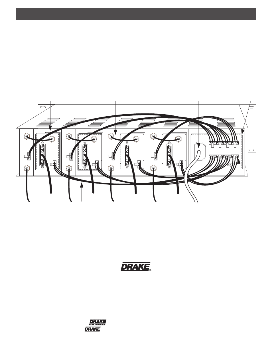
AC POWER CORD
MOLEX CONNECTOR
(TYPICAL)
QAM MODULATOR
DC POWER CABLE
FIGURE 2 - Rear View of System with 4 QAM Modulators and 4 Digital Upconverters.
DIGITAL UPCONVERTER
POWER SUPPLY
Avoid stretching the cables or routing them where damage to
the cable is likely. After the desired modules are installed into
the DRMM12 and the DRMM12 is secured in the rack,
connect the AC power cord of the power supply to a source of
AC power.
First, install the Drake PS8 Power Supply into the DRMM12.
Next, slide individual modules (maximum of 8 units) into the
desired rack locations. Connect the DC power cable,
supplied with each module, between each module and the
PS8 Power Supply.
R.L. DRAKE HOLDINGS, LLC
710 Pleasant Valley Drive
Springboro, OHIO 45066 U.S.A.
CUSTOMER SERVICE AND PARTS TELEPHONE: +1 (937) 746-6990
TELEFAX: +1 (937) 743-4510
WORLD WIDE WEB SITE: http://www.rldrake.com
TM is a trademark of R.L. Drake Holdings, LLC
is a registered trademark of R.L. Drake Holdings, LLC.
© Copyright 2001 R.L. Drake Holdings, LLC
P/N: 651233800A
Printed in the Taiwan.