Input wiring diagram—xa-6004, Channel xa-6004, Front rear – Directed Electronics XA-6004 User Manual
Page 9
9
© 2006 Directed Electronics—all rights reserved
4-CHANNEL XA-6004
LR
INPUT
RR
0.5
4
1.4
LEVEL
HI PASS LOW PASS
REAR
0.5
4
1.4
FRONT
HI PASS
LOW PASS
LEVEL
HI-INPUT
X-OVER
X-OVER
HPF
LPF
FULL
HPF
LPF
FULL
500Hz
50Hz
500Hz
50Hz
500Hz
50Hz
500Hz
50Hz
0.25V
5V
0.25V
5V
90
90
90
90
8dB
0dB
8dB
0dB
BASS
BASS
LF
RF
INPUT
PRT
PWR
1
2
8
9
10
11
4
3
5
6
7
FRONT
REAR
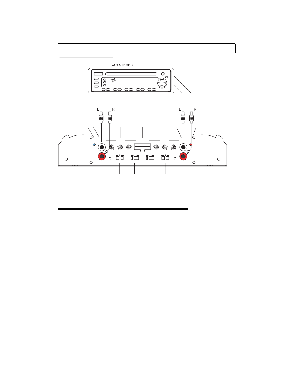
INPUT WIRING DIAGRAM—XA-6004
NNOOTTEE:: The numbers listed below are referenced on the Input Wiring Diagram.
FRONT PANEL CONNECTIONS/CONTROLS—
XA-5001/XA-8001
1. PPW
WRR (LED blue) - when illuminated
indicates that the amplifier is on.
2. HHII IInnppuutt (high level input) - Accepts
1v to 10v input from the headunit’s
speaker output. The amplifier will
automatically wake-up when the
input is greater than 1V.
3. RRCCAA OOuuttppuutt - RCA output to another
amplifier.
4. RRCCAA IInnppuuttss - accepts RCA input from a
source unit, preamplifier, or equalizer.
5. LLeevveell CCoonnttrrooll - continuously adjusts
from 150mV to 5V for full power
output.
6. CCrroossssoovveerr SSw
wiittcchh - activates low
pass crossover, or full (all pass).
7. LLoow
w--PPaassss FFrreeqquueennccyy CCoonnttrrooll - adjusts
the frequency (30Hz–250Hz) of the
lowpass crossover