Hardware installation, Com (serial) ports, Connecting external serial ports – DFI CA331-NR User Manual
Page 35: Bios setting
35
2
Hardware Installation
COM 1
COM 2
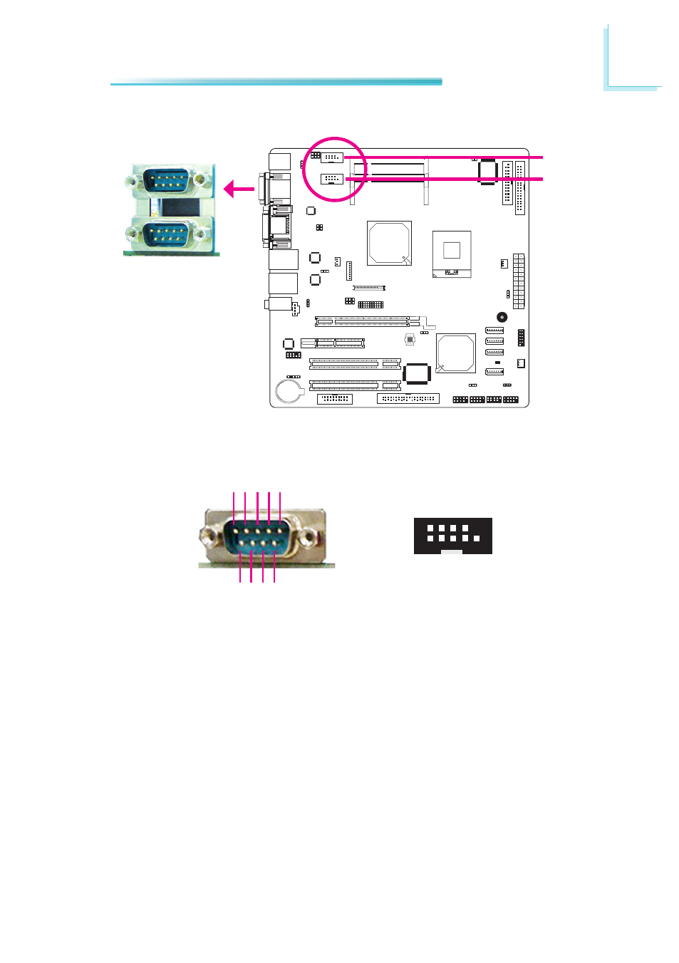
COM (Serial) Ports
COM 3
COM 4
COM 1 and COM 2
DCD-
TD
RD
D
TR
-
GND
1 2 3 4 5
R
T
S-
RI
-
DSR
-
CT
S-
6 7 8 9
COM 1, COM 2 and COM 4 are fixed at RS232.
COM 4
COM 3’s pin definition will vary according to JP3’s settings. Refer to “COM 3
RS232/RS485 Select” in this chapter for more information.
The serial ports are asynchronous communication ports with 16C550A-compatible
UARTs that can be used with modems, serial printers, remote display terminals,
and other serial devices.
Connecting External Serial Ports
Your COM port may come mounted on a card-edge bracket. Install the card-edge
bracket to an available slot at the rear of the system chassis then insert the se-
rial port cable to a COM connector. Make sure the colored stripe on the ribbon
cable is aligned with pin 1 of the COM connector.
BIOS Setting
Configure the serial ports in the Advanced menu of the BIOS. Refer to chapter 3
for more information.
1
9
2
DCD-
TD
GND R
T
S-
RI
-
RD D
TR
-
DSR
-
CT
S-