Appendix e – DFI CD952 series User Manual
Page 62
www.dfi .com
62
Appendix E Digital I/O User Guide
Appendix E
Digital I/O Proramming Guide
1. Pins for Digital I/O
Item
Standard
GPIO80 (Pin111)
GP80
GPIO81 (Pin112)
GP81
GPIO82 (Pin113)
GP82
GPIO83 (Pin114)
GP83
GPIO84 (Pin115)
GP84
GPIO85 (Pin116)
GP85
GPIO86 (Pin117)
GP86
GPIO87 (Pin118)
GP87
GPIO71 (Pin104)
CTR-GP71
GPIO72 (Pin105)
CTR-GP72
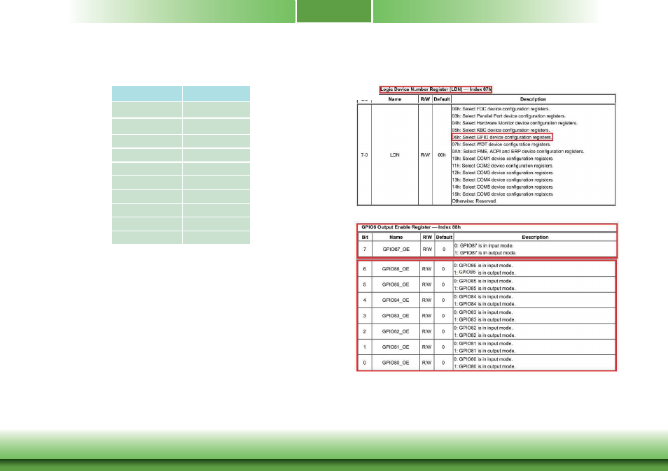
2. Programming Guide
To program the F81866A configuration registers, the following configuration procedures must
be followed in sequence:
(1) Enter the Extended Function Mode
(2) Configure the configuration registers
(3) Exit the Extended Function Mode
The configuration register is used to control the behavior of the corresponding devices. To con-
figure the register, using the index port to select the index and then writing data port to alter
the parameters. The default index port and data port are 0x4E and 0x4F respectively. Pull
down the SOUT1 pin to change the default value to 0x2E/0x2F. To enable configu-
ration, the entry key 0x87 must be written to the index port. To disable configura-
tion, write exit entry key 0xAA to the index port. Following is an example to enable
configuration and disable configuration by using debug.
-o 4e 87
-o 4e 87 (enable configuration)
-o 4e aa (disable configuration)
3. Relative Registers