Rear panel i/o ports, Chapter 2 rear panel i/o ports, Dvi-i port – DFI CD952 series User Manual
Page 15: Bios setting, Driver installation
www.dfi .com
15
Chapter 2 Hardware Installation
Chapter 2
Rear Panel I/O Ports
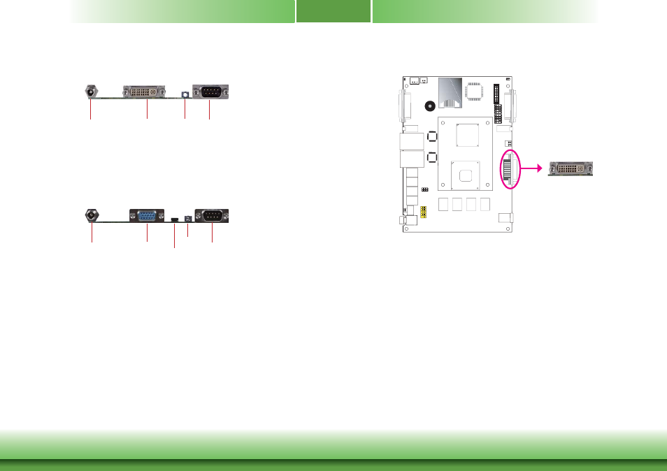
The rear panel I/O ports consist of the following:
• 1 DVI port
• 1 DC-in
• 1 RS232/422/485 COM port or Isolated 4-bit DIO
• 1 Line-out jack
DVI-I
9~24V DC-in
COM
Line-out
VGA
9~24V DC-in
COM 2
Line-out
micro HDMI
The rear panel I/O ports consist of the following:
• 1 micro HDMI port
• 1 VGA port
• 1 DC-in
• 1 RS232/422/485 COM port
• 1 Line-out jack
VGA
1
VGA
/
DVI-I
DVI-I Port
The DVI-I port is used to connect an LCD monitor.
Connect the display device’s cable connector to the DVI-I port. After you plug the cable
connector into the port, gently tighten the cable screws to hold the connector in place.
BIOS Setting
Configure the display device in the Chipset menu (“North Bridge Configuration” submenu) of
the BIOS. Refer to chapter 3 for more information.
Driver Installation
Install the graphics driver. Refer to chapter 4 for more information.
DVI-I