System memory – DFI KB968 User Manual
Page 12
www.dfi .com
Chapter 3 Hardware Installation
12
Chapter 3
System Memory
The system board is equipped with one 204-pin SODIMM socket that supports DDR3
1066/1333/1600MHz
(-420C/-415G/-217G) or 1066/1333MHz (-210H)
memory interface as the
figure shown below.
DDR3
Important:
Electrostatic discharge (ESD) can damage your board, processor, disk drives, add-in
boards, and other components. Perform installation procedures at an ESD workstation
only. If such a station is not available, you can provide some ESD protection by wear-
ing an antistatic wrist strap and attaching it to a metal part of the system chassis. If
a wrist strap is unavailable, establish and maintain contact with the system chassis
throughout any procedures requiring ESD protection.
System Memory
Important:
When the Standby Power LED lit red, it indicates that there is power on the board.
Power-off the PC then unplug the power cord prior to installing any devices. Failure to
do so will cause severe damage to the board and components.
Standby
Power LED
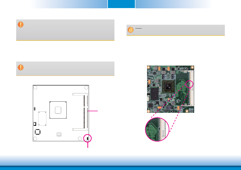
Installing the DIMM Module
1. Make sure the PC and all other peripheral devices connected to it has been powered down.
2. Disconnect all power cords and cables.
3. Locate the SODIMM socket on the system board.
4. Note the key on the socket. The key ensures the module can be plugged into the socket in
only one direction.
Note:
The system board used in the following illustrations may not resemble the actual one.
These illustrations are for reference only.