Chapter 3 – DFI CD9A3 series User Manual
Page 17
www.dfi .com
Chapter 3 Hardware Installation
17
Chapter 3
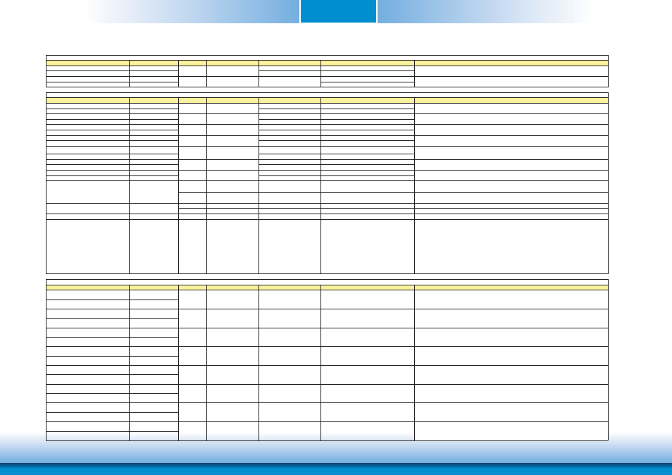
Signal
Pin#
Pin Type
Pwr Rail /Tolerance
CD9A3 Series
Carrier Board
Description
EXCD0_CPPE#
A49
PU 10k to 3.3V
EXCD1_CPPE#
B48
PU 10k to 3.3V
EXCD0_PERST#
A48
EXCD1_PERST#
B47
Signal
Pin#
Pin Type
Pwr Rail /Tolerance
CD9A3 Series
Carrier Board
Description
DDI1_PAIR0+/DP0_LANE0+
B71
Connect AC Coupling Capacitors 0.1uF to Device
DDI1_PAIR0-/DP0_LANE0-
B72
Connect AC Coupling Capacitors 0.1uF to Device
DDI1_PAIR1+/DP0_LANE1+
B73
Connect AC Coupling Capacitors 0.1uF to Device
DDI1_PAIR1-/DP0_LANE1-
B74
Connect AC Coupling Capacitors 0.1uF to Device
DDI1_PAIR2+/DP0_LANE2+
B75
Connect AC Coupling Capacitors 0.1uF to Device
DDI1_PAIR2-/DP0_LANE2-
B76
Connect AC Coupling Capacitors 0.1uF to Device
DDI1_PAIR3+/DP0_LANE3+
B81
Connect AC Coupling Capacitors 0.1uF to Device
DDI1_PAIR3-/DP0_LANE3-
B82
Connect AC Coupling Capacitors 0.1uF to Device
DDI1_PAIR4+
B77
NA
NA
DDI1_PAIR4-
B78
NA
NA
DDI1_PAIR5+
B91
NA
NA
DDI1_PAIR5-
B92
NA
NA
DDI1_PAIR6+
B93
NA
NA
DDI1_PAIR6-
B94
NA
NA
I/O PCIE
AC coupled on Module
PD 49.9K to GND
(S/W IC between Rpu/PCH) Connect to DP AUX+
DP AUX+ function if DDI1_DDC_AUX_SEL is no connect
I/O OD CMOS 3.3V / 3.3V
PU 2.2K to 3.3V, PD 49.9K to
GND
Connect to HDMI/DVI I2C CTRLCLK
HDMI/DVI I2C CTRLCLK if DDI1_DDC_AUX_SEL is pulled high
I/O PCIE
AC coupled on Module
PU 100K to 3.3V
Connect to DP AUX-
DP AUX- function if DDI1_DDC_AUX_SEL is no connect
I/O OD CMOS 3.3V / 3.3V
PU 2.2K to 3.3V/PU 100K to 3.3V Connect to HDMI/DVI I2C CTRLDATA
HDMI/DVI I2C CTRLDATA if DDI1_DDC_AUX_SEL is pulled high
DDI1_HPD/DP0_HPD
B89
I CMOS
3.3V / 3.3V
PD 1M to GND
PD 1M and Connect to device Hot Plug Detect
DDI Hot-Plug Detect
DDI1_DDC_AUX_SEL
B95
I CMOS
3.3V / 3.3V
PD 1M to GND
PU 100K to 3.3V for DDC(HDMI/DVI)
Selects the function of DDI1_CTRLCLK_AUX+ and DDI1_CTRLDATA_AUX-.
This pin shall have a 1M pull-down to
logic ground on the Module. If this input is floating the AUX pair is
used for the DP AUX+/- signals. If pulled-high the AUX pair
contains the CRTLCLK and CTRLDATA signals
************************************************************
DDI[n]_DDC_AUX_SEL shall be pulled to 3.3V on the Carrier with a 100K Ohm
resistor to configure the DDI[n]_AUX pair as the DDC channel.
Carrier DDI[n]_DDC_AUX_SEL should be connected to pin 13 of the DisplayPort
Signal
Pin#
Pin Type
Pwr Rail /Tolerance
CD9A3 Series
Carrier Board
Description
USB0+
A46
USB0-
A45
USB1+
B46
USB1-
B45
USB2+
A43
USB2-
A42
USB3+
B43
USB3-
B42
USB4+
A40
USB4-
A39
USB5+
B40
USB5-
B39
USB6+
A37
USB6-
A36
USB7+
B37
USB7-
B36
ȟ
ȟ
ȟ
ȟ
Connect 90ಳ @100MHz Common Choke in series
and ESD suppressors to GND to USB connector
Connect 90ಳ @100MHz Common Choke in series
and ESD suppressors to GND to USB connector
Connect 90ಳ @100MHz Common Choke in series
and ESD suppressors to GND to USB connector
Connect 90ಳ @100MHz Common Choke in series
and ESD suppressors to GND to USB connector
Connect 90ಳ @100MHz Common Choke in series
and ESD suppressors to GND to USB connector
Connect 90ಳ @100MHz Common Choke in series
and ESD suppressors to GND to USB connector
Connect 90ಳ @100MHz Common Choke in series
and ESD suppressors to GND to USB connector
DDI Signals Descriptions
O PCIE
AC coupled off Module
DDI 1 Pair 0 differential pairs/Serial Digital Video B red output differential pair
O PCIE
AC coupled off Module
DDI 1 Pair 2 differential pairs/Serial Digital Video B blue output differential pair
O PCIE
AC coupled off Module
I/O USB
3.3V Suspend/3.3V
USB differential pairs 4
I/O USB
3.3V Suspend/3.3V
Connect 90ಳ @100MHz Common Choke in series
and ESD suppressors to GND to USB connector
I/O USB
3.3V Suspend/3.3V
USB differential pairs 7, USB7 may be configured as a USB client or as a host, or both, at the
Module designer's discretion.
I/O USB
3.3V Suspend/3.3V
USB differential pairs 6
I/O USB
3.3V Suspend/3.3V
USB differential pairs 5
NA for CD9A3
O PCIE
AC coupled off Module
DDI 1 Pair 3 differential pairs/Serial Digital Video B clock output differential pair.
DDI 1 Pair 1 differential pairs/Serial Digital Video B green output differential pair
USB differential pairs 3
I/O USB
3.3V Suspend/3.3V
USB differential pairs 2
I/O USB
3.3V Suspend/3.3V
USB differential pairs 1
USB Signals Descriptions
I/O USB
3.3V Suspend/3.3V
USB differential pairs 0
DDI1_CTRLCLK_AUX+/DP0_AUX+
B98
DDI1_CTRLCLK_AUX-/DP0_AUX-
B99
NA for CD9A3
NA for CD9A3
ExpressCard Signals Descriptions
I CMOS
3.3V /3.3V
PCI ExpressCard: PCI Express capable card request, active low, one per card
O CMOS
3.3V /3.3V
PCI ExpressCard: reset, active low, one per card