Equipment, Technical data – Dexaplan VT 623 User Manual
Page 2
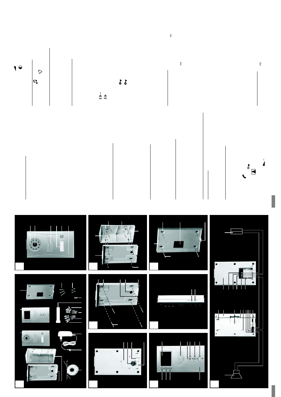
Equipment
Package
contents
(see
Fig
.A):
Outdoor
station
front
side
(see
Fig
.B):
Outdoor
station
rear
side
(see
Fig
.C):
Outdoor
station
wall
brack
et
(see
Fig
.D):
W
all
brack
et
fixing
for
outdoor
station
on
wedge
shaped
brack
et
(see
Fig
.E):
Indoor
station
front
side
(see
Fig
.F):
1
outdoor
station
2
indoor
station
3
wall
bracket
for
indoor
station
4
fixing
screws
5
fixing
for
wedge
shaped
bracket
6
spare
fuse
7
spare
nameplate
8
wall
plugs
for
indoor
station
9
mounting
screws
for
indoor
station
10
mounting
screws
for
outdoor
station
11
wall
plugs
for
outdoor
station
12
mains
adapter
13
low-voltage
connector
14
connection
cable
15
bracket
for
outdoor
station
16
wall
bracket
for
outdoor
station
17
infrared
LEDs
18
camera
lens
19
loudspeaker
20
illuminated
nameplate
cover
21
doorbell
button
22
microphone
23
terminal
cover
24
grommet
25
cable
channel
26
tab
27
hole
for
mounting
screw
28
cable
opening
(for
laying
along
the
wall)
29
cable
opening
(for
laying
through
the
wall)
30
hole
for
fixing
31
hole
for
mounting
screw
32
cable
opening
33
monitor
34
loudspeaker
35
operating
status
LED
36
talk
button
37
door
release
button
38
monitor
button
39
microphone
40
reduce
volume
button
screws
wedge
shaped
screw
41
increase
volume
button
42
image
adjustment
button
43
chime
switch
44
chime
volume
switch
45
hole
for
mounting
screw
46
cable
opening
47
hole
for
fixing
48
optional
powered
loudspeaker
(not
supplied)
49
keyhole
slot
50
connection
for
low-voltage
current
51
cable
channel
52
fuse
holder
53
terminal
for
powered
loudspeaker
54
terminal
for
powered
loudspeaker
55
connecting
cable
terminal
56
connecting
cable
57
connection
for
optional
electric
door
release
58
connection
for
optional
electric
door
59
connecting
cable
60
connecting
cable
61
nameplate
62
optional
electric
door
(not
supplied)
Operating
voltage:
from
the
indoor
station
(15
V
DC)
Po
wer
consumption:
max.
1
A
Voltage
for
door
:
12
V
DC
(max.
1
A)
*
Camera
image
sensor:
1/3“
CMOS
colour
Camera
image
resolution:
628
x562
pixels
(P
AL)
Camera
lens:
f=
4.5
mm
Camera
angle
of
view:
approx.
64°
horizontal,
approx.
48°
vertical
Illumination:
9
infrared
LEDs
(for
illumination
of
the
close
range
during
darkness)
Twilight
switch:
activates
infrared
LEDs
at
approx.
2
Lux
Dimensions:
approx.104
x185
x46
mm
incl.
wall
bracket
Casing
material:
PC,
ABS
Weight:
approx.
333
g
incl.
wall
bracket
Operating
temperature:
-10
°C
to
+50
°C
Protection
class:
IP
55
*
The
door
opener
must
meet
these
specifications
Operating
voltage:
15
V
DC
Power
consumption:
max.
1.5
A
Indoor
station
side
(see
Fig
.G):
Indoor
station
wall
brack
et
(see
Fig
.H):
Connection
diagram
(see
Fig
.I):
Outdoor
station
VT
623C
Indoor
station
VT
623M
Technical
data
screw
terminal
release
terminal
terminal
release
V
release
B
C
D
F
I
G
10
15
17
18
19
20
21
22
23
24
25
26
27
16
16
28
29
30
33
34
35 36
37
38
39
40
41
42
43
44
E
31
48
49
50
2
51 52
61
1
60
59
58
57
53 54 55 56
62
45
46
47
H
9
3
5
10
32
A
1
2
3
4
5
6
7
8
9
10
11
12
15
13
16
14
GB
/IE
-
3
GB
/IE
-
4
A
A
B
B
+
1/2/3
+