Section 2: mechanical installation, Mechanical, Installation -1 – Daktronics AB-1600-1.5,2.5 User Manual
Page 11
Mechanical Installation
2-1
Section 2 : Mechanical Installation
i
Daktronics engineering staff must approve any changes that may affect the weather tightness of
the display. This includes, but is not limited to the border shrouding, back sheets, cooling fans, fan
filters and filler panels. If ANY modifications are made to the weather tightness of the display,
detailed drawings of the changes MUST BE submitted to our engineering staff for evaluation and
approval or the warranty will be null and void.
2.1
Display Definitions
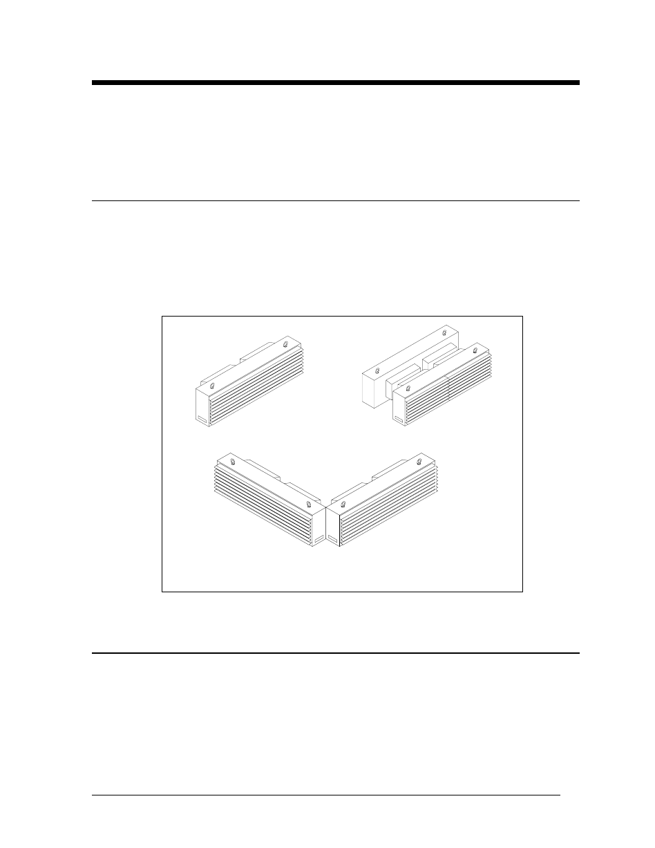
Line displays are offered in single and multiple face displays. Figure 1 illustrates a single
face display and two 2V display configurations. The single face display is a single-sided,
independent display. The multiple face display may consist of two independent displays or, if
Venus
T 1500 controlled, of an independent (master) and a dependent (slave) display.
On 2V displays, regardless of the controller type, signal interconnection will be required
between multiple faces.
2.2
Eye Bolts
The top of the display will be equipped with eye bolts which are used to lift the display into
position. Special precautions must be taken to ensure that the rated load of the eye bolts is
not exceeded. Refer to the section in Appendix B labeled Eye Bolts to determine the
allowable load of the eye bolts shipped with the display.
SINGLE FACE
2V BACK-TO-BACK
2V APEX
Figure 1: Sample Display Configurations