Daktronics AB-1600-1.5,2.5 User Manual
Page 65
Maintenance & Troubleshooting
4-21
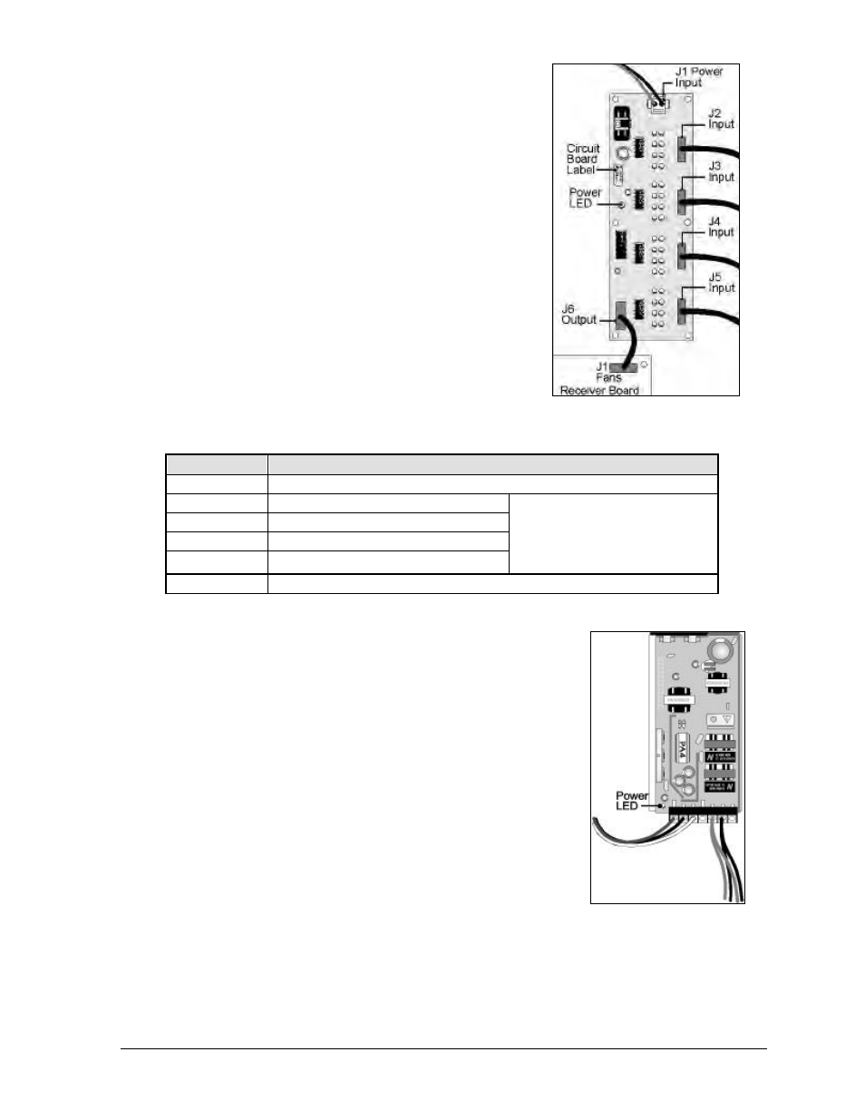
The fan controller expander board, Figure 61 is part of the data
distributor. Each of the LEDs on the fan control expander board
corresponds to a fan controller in the display. All the LEDs must
be ON for the display to operate. An OFF LED indicates a fan
controller is reporting a bad fan. At that point, check that fan
controller to determine which fan is failing.
The table below lists the connectors of the fan control expander
board along with their functions.
Connector
Function
J1
Power input from power supply
J2
Input from fan controllers 1-8
J3
Input from fan controllers 9-16
J4
Input from fan controllers 17-24
J5
Input from fan controllers 25-32
NOT ALL INPUTS
(J2-J5) ARE USED ON EVERY
DISPLAY. ANY UNUSED INPUTS
MUST HAVE A TERMINATOR
PLUG.
J6
Output fan controller reports to J1 on receiver board
Column Director Power Supply
There is one column director power supply per display section.
These power supplies are found mounted on brackets within the
display.
Each column director power supply has a power indicator LED,
Figure 62. If this LED is on, the unit is working. Refer to Drawing
A-119453 in Appendix B.
Figure 61: Fan Controller
Expander Board
Figure 62: Column
Director Power Supply