Daktronics AB-1600-1.5,2.5 User Manual
Page 37
Electrical Installation
3-11
3.9
Data Distributor Electrical Installation
Reference Drawings:
Schematic, Power & Wiring 220V ...........................................................Drawing A-127543
Schematic, Power & Wiring 230V ...........................................................Drawing A-127544
Schematic, Power & Wiring 240V ...........................................................Drawing A-127545
If the display has a data distributor, follow these steps to complete power, signal and internal
temperature monitoring system connections. For a description of the difference between a display
with a line receiver and a data distributor, refer to sub-section 1.2 Display Overview.
Connecting Power to the Data Distributor
Whenever possible, Daktronics runs power from the display or section panelboard to the data
distributor prior to shipment. However, certain situations may require this power be run in the field.
Power should be run in conduit to the base of the data distributor enclosure. On the bottom of the
enclosure are knockouts for conduit attachment. Conduit and labor to pull the power cable is the
responsibility of the customer or contractor unless otherwise stated.
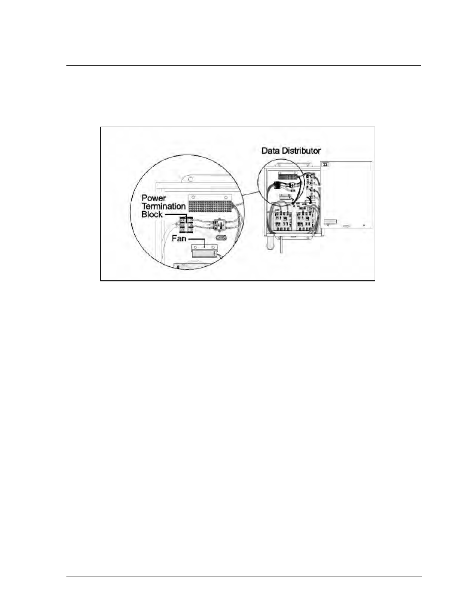
Having removed the front cover of the data distributor, the power cable can be pulled to the power
termination block in the upper-left hand corner of the enclosure. The upper-left hand corner of the
data distributor is illustrated in Figure 31.
This termination block has a protective plate that must be removed to connect the hot, neutral and
ground wires. Strip and connect the incoming wires in agreement with the labels beside the
termination block.
Figure 31: Close-up view of the power termination block in the data distributor