2 power wiring, 2 power wiring -3 – Daktronics CH-1036H User Manual
Page 9
Installation
2-3
At the control location, mount the signal J-box to a convenient location. Route the
cables and connect to the wires leading from the connector in the cover according to
the table below and Drawing A-47207.
At the display, open the bottom hinged panel covering the entrance enclosure as
shown on Drawing A-51804. Remove the cover from the entrance enclosure. Refer
to Drawing A-46755 for an illustration of the components inside the entrance
enclosure. Connect the signal wires to TB31 as indicated in the table below.
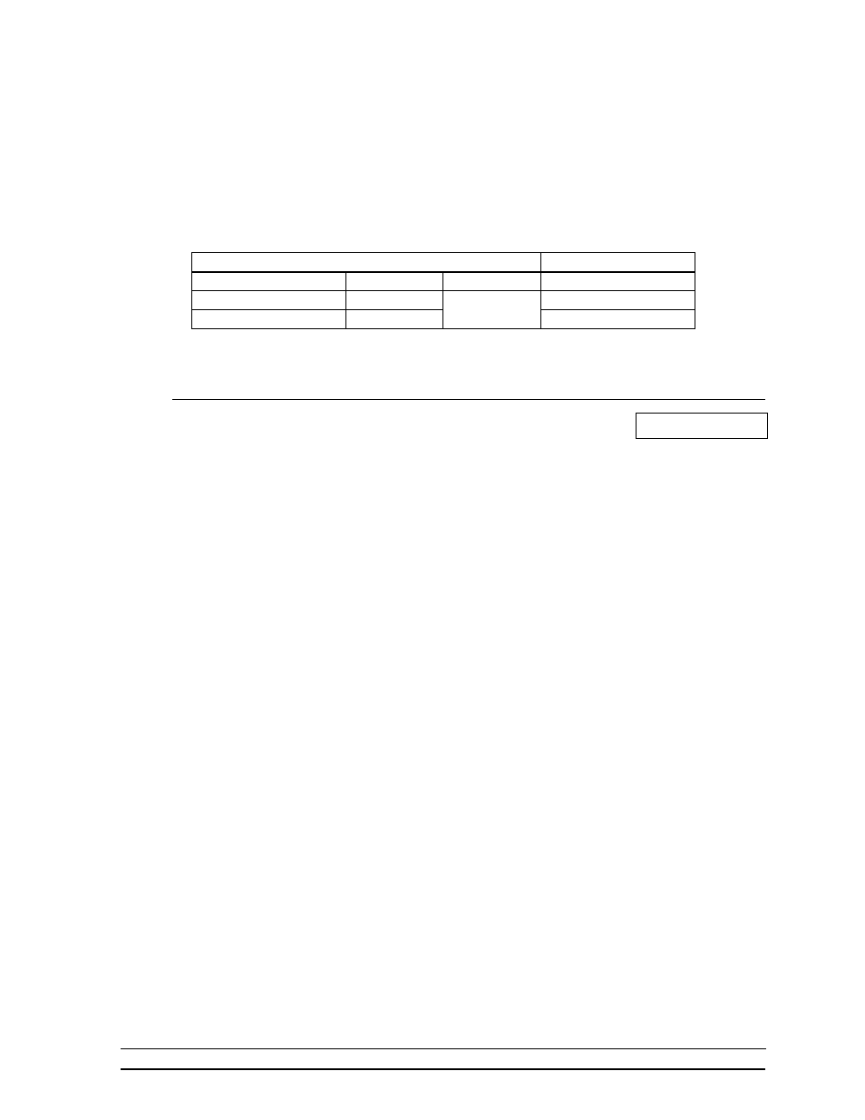
Control End
Display End
J-box Terminal No.
Wire Color
Output No.
TB31 Terminal No.
14 Red/Wht
1*
1
(+)
15 Grn/Wht
2
(-)
*Auxiliary display(s) require(s) a different output no.(s). Consult your CHTS-300 console
manual.
2.4.2 Power Wiring
Reference Drawing: Pwr/Sig Entrance, 1 Driver Display.... Drawing A-46755
The CH-1036H display requires a 120/240 VAC, 40 amp circuit per line. When
equipped with 25W lamps, the maximum current draw is 45 amps. When equipped
with 30W, 30R20 reflector lamps, the maximum current draw is 54 amps.
Route power wires into the display and connect to TB41 in the entrance enclosure, as
shown in Drawing A-46755.
Connect the ground wire to E41 and to a ground rod near the display, according to
local codes.