4 electrical installation, 1 control signal cable, 2 power wiring – Daktronics CH-1624V User Manual
Page 9: 2 power, Wiring -3
Installation
2-3
2.4 Electrical
Installation
2.4.1 Control Signal Cable
Reference Drawings: Pwr/Sig Entrance, 1 Driver Display.. Drawing A-46755
Component Locations, CH-1624V... Drawing A-46756
Color Code, 25 Pin J-Box................ Drawing A-47207
For the display, two conductors of 24 AWG are needed. For distances up to 600 ft. or
22 AWG, up to 1000 ft. are required. Daktronics has 24 AWG direct burial cable,
Daktronics part no. W-1105 with 6 conductors, and 22 AWG cable that must be
pulled through the conduit before burial, Daktronics part no. W-1077 with 2
conductors.
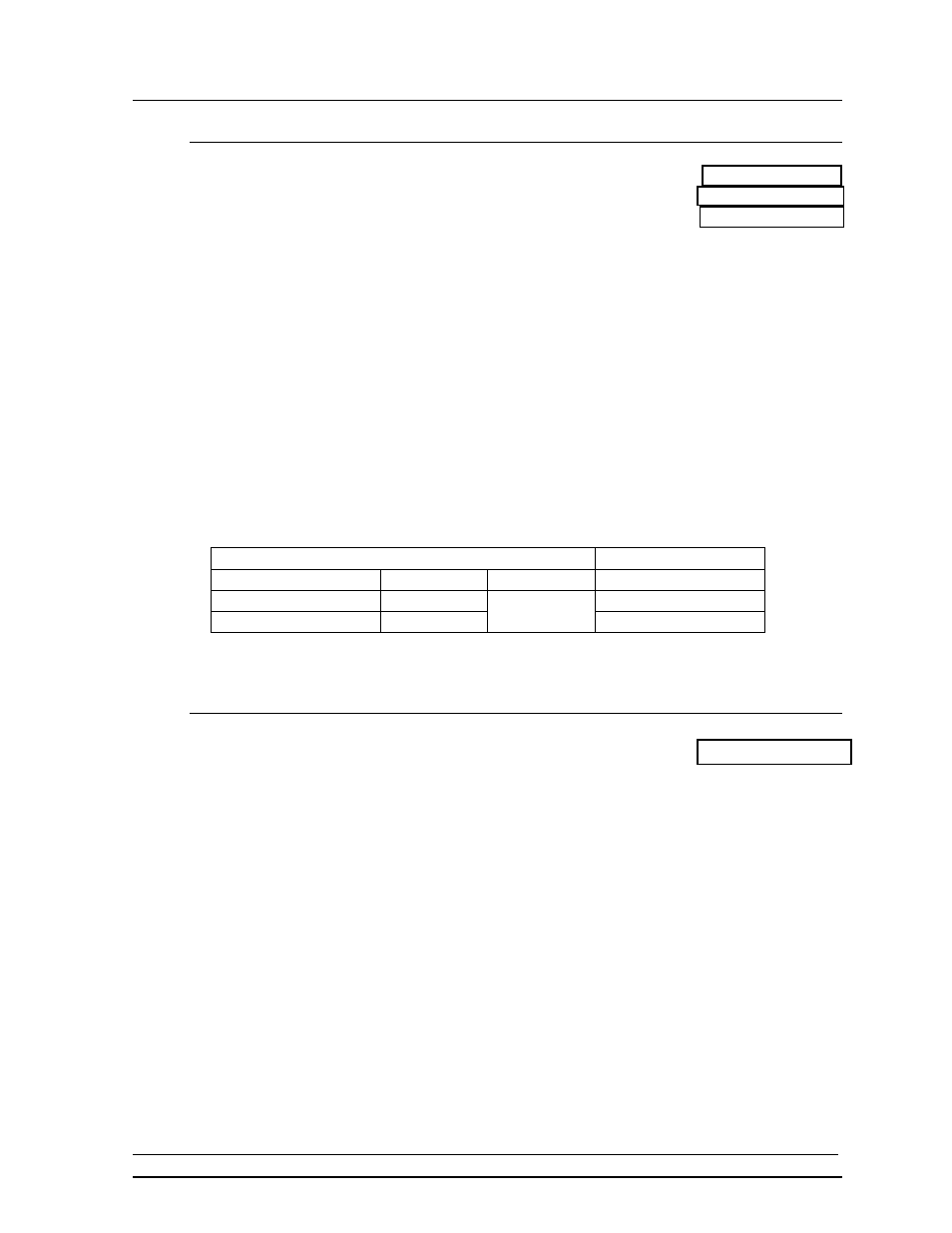
At the control location, mount the signal J-box to a convenient location. Route the
cables and connect to the wires leading from the connector in the cover according to
the table below and Drawing A-47207.
At the display, open the bottom hinged panel covering the entrance enclosure as
shown in Drawing A-46756. Remove the cover from the entrance enclosure. Refer
to Drawing A-46755 for an illustration of the components inside the entrance
enclosure. Connect the signal wires to TB31 as indicated in the table below.
Control End
Display End
J-box Terminal No.
Wire Color
Output No.
TB31 Terminal No.
14 Red/Wht
1*
1
(+)
15 Grn/Wht
2
(-)
*Auxiliary display(s) require(s) a different output number(s). Consult the CHTS-300 console manual.
2.4.2 Power
Wiring
Reference Drawing: Pwr/Sig Entrance, 1 Driver Display.... Drawing A-46755
The CH-1624V display requires a 120/240 VAC, 40 amp circuit per line. When
equipped with 25W lamps, the maximum current draw is 66.67 amps. When
equipped with 30W, 30R20 reflector lamps, the maximum current draw is 80 amps.
Route power wires into the display and connect to TB41 in the entrance enclosure, as
shown in Drawing A-46755.
Connect the ground wire to E41 and to a ground rod near the display, according to
local codes.