Installation, Warning: never check for gas leaks with open flame – Design Dynamics VTD-24N-JHB User Manual
Page 9
www.desatech.com
114370-01E
9
INSTALLATION
Continued
4.. Place. log. set. assembly. in. center. of.
fireplace. floor.. Make. sure. front. faces.
forward.
5.. Install.gas.connector.tube.into.gas.supply.
fitting. Carefully shape tube to attach to
adapter fitting being careful not to kink
tube.
6.. Install. provided. gas. connector. tube.
into the gas inlet fitting (see Figure 7,
page 8).
7. Test for leaks following instructions under
Testing Burner for Leaks.
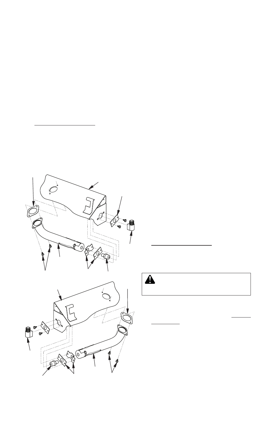
Repositioning Gas Inlet to Left Side of
Unit
1. Remove venturi and gasket by unscrew-
ing two screws under chassis (see
Figure 8).
2. Unthread elbow fitting from orifice (see
Figure 8).
3. Remove orifice and brackets by unscrew-
ing two screws on right side of unit (see
Figure 8).
4. Install orifice and brackets into left side of
unit using screws removed in step 1.
5.. Install. venturi. and. gasket. under. bottom.
burner and into repositioned orifice and
brackets (see Figure 8).
6. Thread elbow fitting back into orifice. Ap-
ply thread sealant to orifice threads (see
Figure 8).
7.. Install. gas. connector. tube. that. comes.
with log set into gas inlet fitting (see
Figure 8).
8. Install supplied brass adapter fitting that
comes with log set into fireplace gas
supply. pipe.. Use. thread. sealant. (see.
Figure 8).
9.. Place. log. set. assembly. in. center. of.
fireplace. floor.. Make. sure. front. faces.
forward.
10..Install.gas.connector.tube.into.gas.supply.
fitting. Carefully shape tube to attach to
adapter fitting. Be careful not to cause
kinks.in.tube.
11. Test for leaks following instructions under
Testing Burner for Leaks.
TESTING BURNER FOR LEAKS
1.. Generously.apply.noncorrosive.leak.de-
tection fluid to all connections.
WARNING: Never check for
gas leaks with open flame.
2. Light burner with shutoff valve no more
than. half. open. and. holding. a. match.
slightly.in.front.of.the.pan.(see.Lighting
Instructions, page 10).
3. Inspect all connections for bubbles, raw
gas odors, or flame from any area other
than burner. If leaks are detected, shut
off. gas. valve. immediately.. Tighten. or.
reassemble.the.loose.connections.using.
pipe joint compound until burner system
is.leak.free.
4. When finished testing, turn gas shutoff
valve OFF to extinguish all flames.
Figure 8 - Repositioning Gas Inlet to Left
Side of Unit
Outer.
Bracket
Gasket
Venturi
Screws
Inner.
Brackets
Orifice
Elbow
Fitting
Elbow
Fitting
Inner.Brackets
Orifice
Gasket
Venturi
Screws
Chassis
Chassis