Section 3: maintenance, 1 replacement of the wifi client radio, Section 3 – Daktronics WiFi Communication User Manual
Page 11: Maintenance, Replacement of the wifi client radio
Maintenance
5
Section 3:
Maintenance
3.1
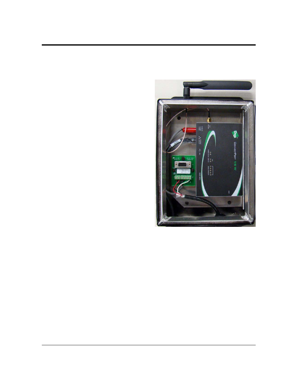
Replacement of the WiFi Client Radio
The WiFi client radio is located in the signal termination enclosure mounted at the display.
To replace a client radio, first disconnect
the power and signal connections (refer to
Figure 4
for connector locations).
Figure 4: Signal Enclosure
1. The radio and breakout board are
attached to the enclosure mounting
plate. Disconnect all signal cables
and power wires and remove the
mounting plate from the enclosure
by removing the three screws.
2. Lift out the mounting plate.
3. The radio is held to the mounting
plate by two screws (the break out
board is held in place by three
screws).
4. Release only the two screws that
hold the radio in place.
5. Attach the new radio to the
mounting plate.
6. Replace the mounting plate in the
enclosure using the three screws
and reconnect power and signal
cables.
7. The radio has the following input and output jacks:
a. The Ethernet input jack is labeled “ETHERNET LINK ACT”. Ethernet cable
is connected to this jack from the display.
b. The radio’s external antenna is connected to the jack labeled “Wi-Fi
ANTENNA”.
c. Power is routed through the break out board to the “6-30 VDC” location.