Replacing a driver, Setting the driver address, 4 schematics – Daktronics BB-2140 Transparent Shot Clock User Manual
Page 21: Schematics
Scoreboard Troubleshooting
15
Replacing a Driver
If the driver status indicators do not appear to be working correctly, it may be necessary to
replace the driver.
1. Open the control enclosure by removing the 6 screws and swinging the door open.
2. Disconnect all connectors from the driver by squeezing together the locking tabs and
pulling the connectors free.
Note: It may be helpful to label the cables to know which cable goes to which
connector when reattaching the driver.
3. Remove the 4 nuts securing the driver to the enclosure door.
4. Carefully lift the driver from the enclosure and place it on a clean, flat surface.
5. Position a new driver over the standoffs and tighten the nuts.
6. Reconnect all power/signal connectors.
Note: The connectors are keyed and will attach in one way only. Do not attempt to
force the connections.
7. Ensure the driver is set to the correct address (refer to Setting the Driver Address).
8. Close and secure the enclosure door, then power up and test the scoreboard to see if
changing the driver has resolved the problem.
Setting the Driver Address
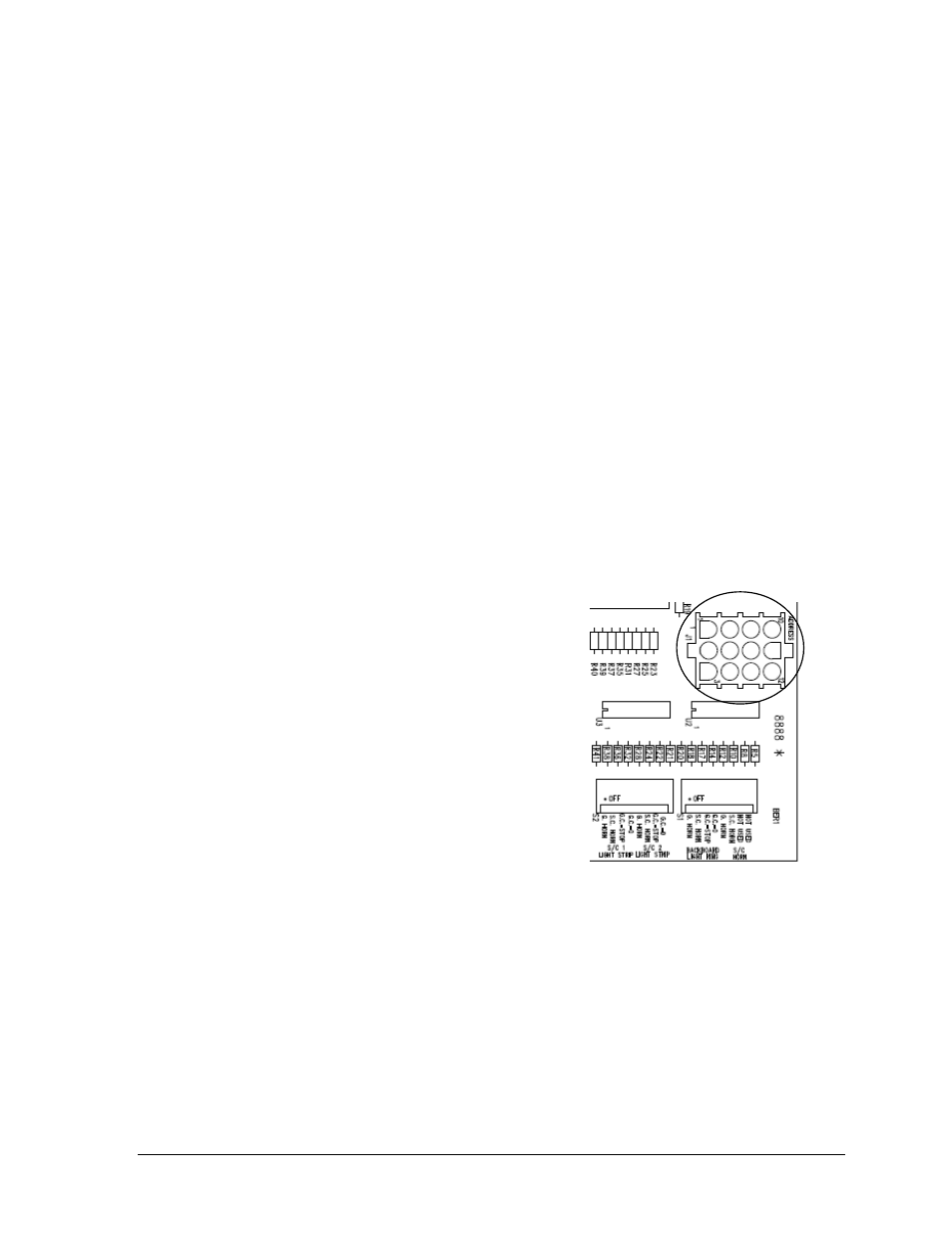
Since the same LED drivers can be used for many
scoreboard models, each driver must be set to receive
the correct signal input, or address, for the model
being used. This address is set with jumper wires in a
12-pin plug which mates with jack J1 on the driver
(Figure 7).
After replacing the driver in the control enclosure, be
sure to use an Address 1 plug in jack J1. In most cases,
the same plug can be reused from the driver that was
replaced; otherwise, one may be ordered from
Daktronics (part number 0A-1150-0122).
Note: For BB-2150 and BB-2151 to display 1/10 of
a second, switch 8 of DIP switch S3 must be set to ON.
Refer to Drawing B-216653 in Appendix A for more information on DIP switch settings.
5.4 Schematics
For advanced scoreboard troubleshooting and repair, it may be necessary to consult the
schematic drawings. Drawing B-216653 in Appendix A shows detailed power and signal
wiring diagrams of internal display components such as drivers, transformers, and horns.
Note: The schematic drawing also shows the DIP switch settings that control when the
horn sounds and when the LED light strips turn on.
Figure 7: Address Jack J1