3 power-on self-test (post), Radio settings, 4 signal connection – Daktronics BB-2140 Transparent Shot Clock User Manual
Page 16: Power-on self-test (post), Signal connection
10
Electrical Installation
4.3 Power-On Self-Test (POST)
The scoreboard performs a self-test each time that power is turned on and the control console
is powered off or not attached to the scoreboard. If the control console is attached and
powered on, the self-test does not run, and data from the control console is displayed on the
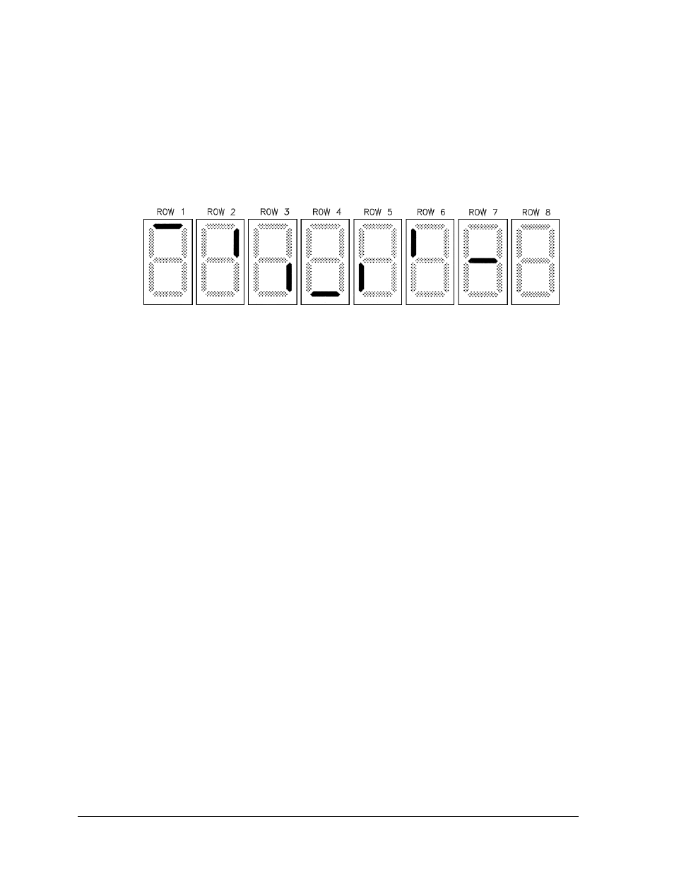
scoreboard after a brief period of time. Each scoreboard self-test pattern will vary depending
on the scoreboard model, the number of drivers and types of digits. Figure 4 shows an
example of the LED bar test pattern that each digit performs.
Radio Settings
If a radio receiver is installed (see Section 6.2), the radio broadcast settings (“b1”) and the
channel settings (“C1”) will be displayed in the game clock digits during the POST. These
values must match the settings in the control console (refer to the appropriate control console
manual listed in Section 1.4).
4.4 Signal Connection
Signal installation requires routing cable from the control console to a signal junction box near
the display, routing cable from the junction box to the control enclosure, and routing the
appropriate cables from the system components to the control enclosure.
1. At a minimum, use a paired, 22 AWG shielded cable (Daktronics part number W-
1077) and connect the cable to a ¼" J-box at the control console end.
2. Route the cable from the J-box on the control console end to a J-box near the display.
3. Install the ¼ inch phone plug cable (Daktronics part number 0L-40683) to the
scoreboard end of the cable. Be sure to connect the cable shielding only in the J-box
on this end.
Note: DO NOT connect cable shielding at the J-box near the control console.
4. Insert the plug into the Signal In (J31) jack on the front of the control enclosure.
5. Connect the shot clock(s), remote horn enclosure, and any optional light strip kits to
the appropriate jacks on the control enclosure as shown in Drawing A-184789 and
Drawing A-1060264 in Appendix A.
6. Connect a signal cable from the J-box to the J1, J2, or J3 jack on the back of the All
Sport 5000 console. Also connect the Shot Clock Start/Stop Switch (Daktronics part
number 0A-1196-0031) to the J7 jack on the All Sport 5000.
Figure 4: Digit Segment POST