Fiber optic, 4 power/signal connections between sections, Power/signal connections between sections – Daktronics FB-2500 Modular LED Football Scoreboard User Manual
Page 20: On 3.4
14
Electrical Installation
Fiber Optic
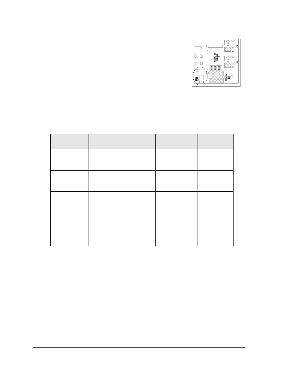
Another common signal communication method is fiber optic
cabling. A minimum cabling of multi-mode, 62.5/125 um, and 2-
core fiber cable is recommended (part # W-1242). The fiber optic
cable is terminated to a male ST-type connector and plugged into
the mating J26 FIBER jack on the driver (Figure 16). This method
requires a signal converter between the All Sport console’s
scoreboard output and the fiber optic cable (not provided by
Daktronics).
3.4 Power/Signal Connections Between Sections
The table below lists the scoreboard sections that do not receive main power or signal:
Information
Shown
Model #
Driver/Power
Supply Location
Power/Signal
Connections*
T.O.L. (HOME)
FB-2531, FB-2533, FB-2536,
FB-2538, FB-2540, FB-2545
HOME Score
A1 J1
PS1 J1
A1 J50
T.O.L. (GUEST)
FB-2571, FB-2573, FB-2575,
FB-2577, FB-2579, FB-2583
GUEST Score
A1 J10
PS1 J10
A1 J50
DOWN
FB-2618, FB-2628, FB-2658
TO GO
A1 J3
PS1 J3
A1 J42B
Mod 1 J2
QTR (quarter)
FB-2621, FB-2631, FB-2661
BALL ON
A1 J8
PS1 J8
A1 J42B
Mod 4 J1
* For HOME T.O.L. sections built prior to September 2013, the digit connects to J14 on
A1/PS1. For GUEST T.O.L. sections, the digit connects to J15 on A1/PS1. Backlit/
electronic captions for either section connect to J42B.
The T.O.L., DOWN, and QTR sections may have up to four connections:
Route the 9-pin plug into the adjacent section and connect to the appropriate jack on
the primary (A1) driver.
Route the 2-pin plug into the adjacent section and connect to the appropriate jack on
the Power Supply (24"+ white LED digits or 36"+ red/amber LED digits only).
If the section includes a backlit or electronic caption, a 5-pin plug must be connected
to the power/signal interconnect cable coming from the primary (A1) driver.
A ribbon cable must be connected between the last mod of the DOWN and BALL ON
electronic captions to the first mod of the TO GO and QTR electronic captions.
Figure 16: Driver Fiber
Connection Location