2 power-on self-test (post), Radio settings, 3 signal connection – Daktronics FB-2500 Modular LED Football Scoreboard User Manual
Page 19: Power-on self-test (post), Signal connection
Electrical Installation
13
Certain scoreboard sections do not receive power via terminal block. Instead, an interconnect
harness routes from the nearest scoreboard section. Refer to Section 3.4.
Note: If a power receptacle is needed to operate the control console at the scoreboard for
troubleshooting, Daktronics recommends that an installation electrician provides a 120 V
outlet close to the disconnect box specifically for this purpose.
3.2 Power-On Self-Test (POST)
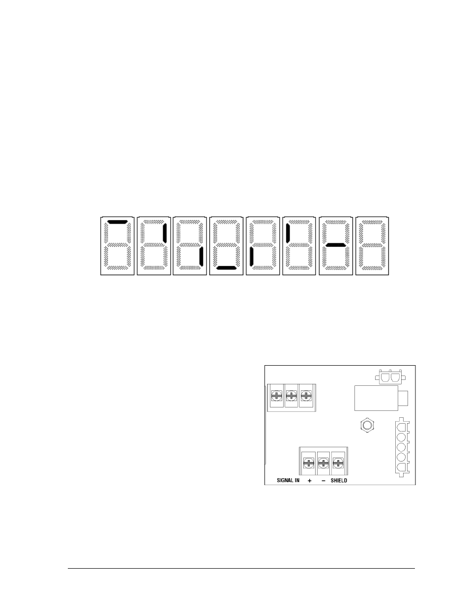
The scoreboard performs a self-test each time that power is turned on and the control console
is powered off or not attached to the scoreboard. If the control console is attached and
powered on, the self-test does not run, and data from the control console is displayed on the
scoreboard after a brief period of time. Each scoreboard self-test pattern will vary depending
on the scoreboard model, the number of drivers and types of digits. Figure 14 shows an
example of the LED bar test pattern that each digit performs.
Radio Settings
If a radio receiver is installed, the radio Broadcast settings (“b1”) and Channel settings (“C1”)
will be displayed in the clock digits during the POST. These values must match the settings in
the control console (refer to the manual listed in Section 1.1).
3.3 Signal Connection
For wired setups, route signal cable from the
control location into the conduit knockout on
the rear of the scoreboard to the signal surge
arrestor card (Figure 15), located just above the
main termination block in the driver enclosure.
At the SIGNAL IN terminal block, connect red
signal wire to positive (+) and black signal wire
to negative (–).
Note: Be sure to properly connect the
shield (silver) wire to the SHIELD terminal.
To connect signal to additional scoreboard sections, route signal wire from SIGNAL OUT on
the main terminal block (Figure 13) of one section to SIGNAL IN on the signal card of another.
For signal cable, Daktronics recommends, as a minimum, single-pair, shielded cable, 22 AWG
(part # W-1077). Two-pair shielded cable (part # W-1234) is preferred.
Figure 14: Digit Segment POST
Figure 15: Signal Surge Arrestor Card