Replacing a driver – Daktronics TI-2020 Multipurpose Track & Field LED Timing Display User Manual
Page 29
Display Maintenance
23
Each driver has numerous connectors providing power and signal inputs and outputs to the
digits and indicators. The table below shows the function of the primary connectors for an 8-
column MASC driver:
Connector #
Function
1
– 8
Output to digits and indicators
17
Main power & signal
18
Horn Relay
19
Address
28
Switches
Refer to Drawing A-167237 in Appendix A for detailed driver pin out/switch specifications.
Replacing a Driver
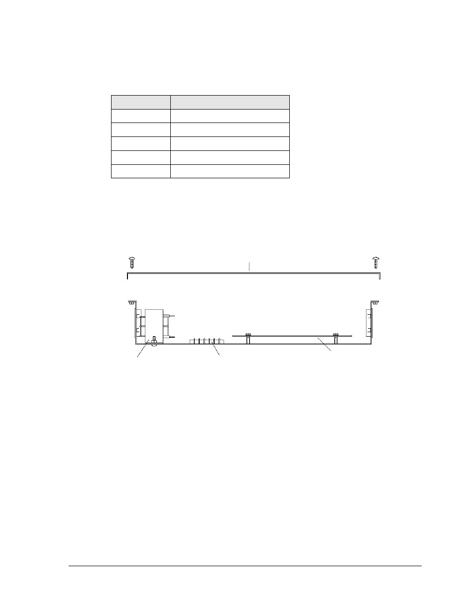
Each driver is enclosed with a transformer and signal termination block (Figure 12).
Before a failed driver can be reached, the enclosure must be accessed. Follow these steps:
1. Open the digit panel as described in Section 6.1.
2. Remove the screws to take off driver enclosure cover.
3. Disconnect all connectors from the driver circuit board by squeezing together the
locking tabs and pulling the connector free.
Note: It may be helpful to label the cables to know which cable goes to which
connector when reattaching the new driver circuit board.
4. Remove the nuts securing the driver circuit board to the inside of the enclosure.
5. Carefully lift the driver from the display and place it on a clean, flat surface.
6. Position a new driver over the screws and tighten the nuts.
Figure 12: Driver Enclosure Assembly
Transformer
Driver Circuit Board
(mounted on standoffs)
Enclosure Cover
Signal Termination Block