3 replacing colons & the breakout board, Replacing colons & the breakout board – Daktronics TI-2020 Multipurpose Track & Field LED Timing Display User Manual
Page 27
Display Maintenance
21
6.3 Replacing Colons & the Breakout Board
When a digit malfunctions, it is necessary to replace the entire digit circuit board. Smaller
components such as colons, however, are constructed in segments, and it may be possible to
make repairs by removing only the defective segment.
Note: Do not attempt to remove individual LEDs.
As with digits, the colon segment circuit boards are mounted to the back of the digit panel.
Unlike individual digits, which connect directly to the driver, the colon segments are
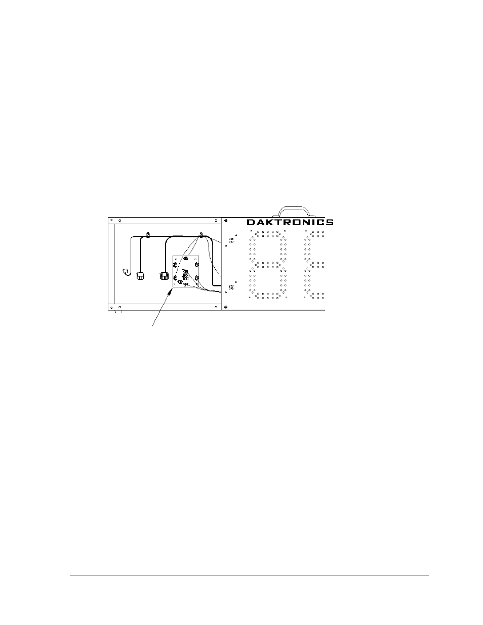
connected to a breakout board, as shown in Figure 10. The breakout board, in turn, connects
to the driver. The breakout PCB is located immediately to the left of the driver and is
accessible through the far left digit panel when viewing the front of the display.
To remove a single colon segment, follow these steps:
1. Open the digit panel as described in Section 6.1.
2. Disconnect the 2-pin power/signal connector from the back of the segment by
squeezing together the locking tabs and pulling the connector free.
3. The segments are secured to the inside of the panel with fixed machine screws,
spacers, and hex nuts. Remove the nuts and lift the segment off the standoff screws.
4. Position a new segment over the screws and tighten the nuts.
5. Reconnect the power/signal connector.
Note: This is a keyed connector and it will attach in one way only. Do not attempt to
force the connection.
6. Close and secure the digit panel, then power up and test the display to see if
changing the digit has resolved the problem.
Figure 10: Breakout Board Location (Digit Panel Removed To Show Interior)
Breakout
Board