Setting the driver address, Segmentation and digit designation, Schematics – Daktronics GM-2101 LED Gymnastics Scoreboards User Manual
Page 19: Replacement parts
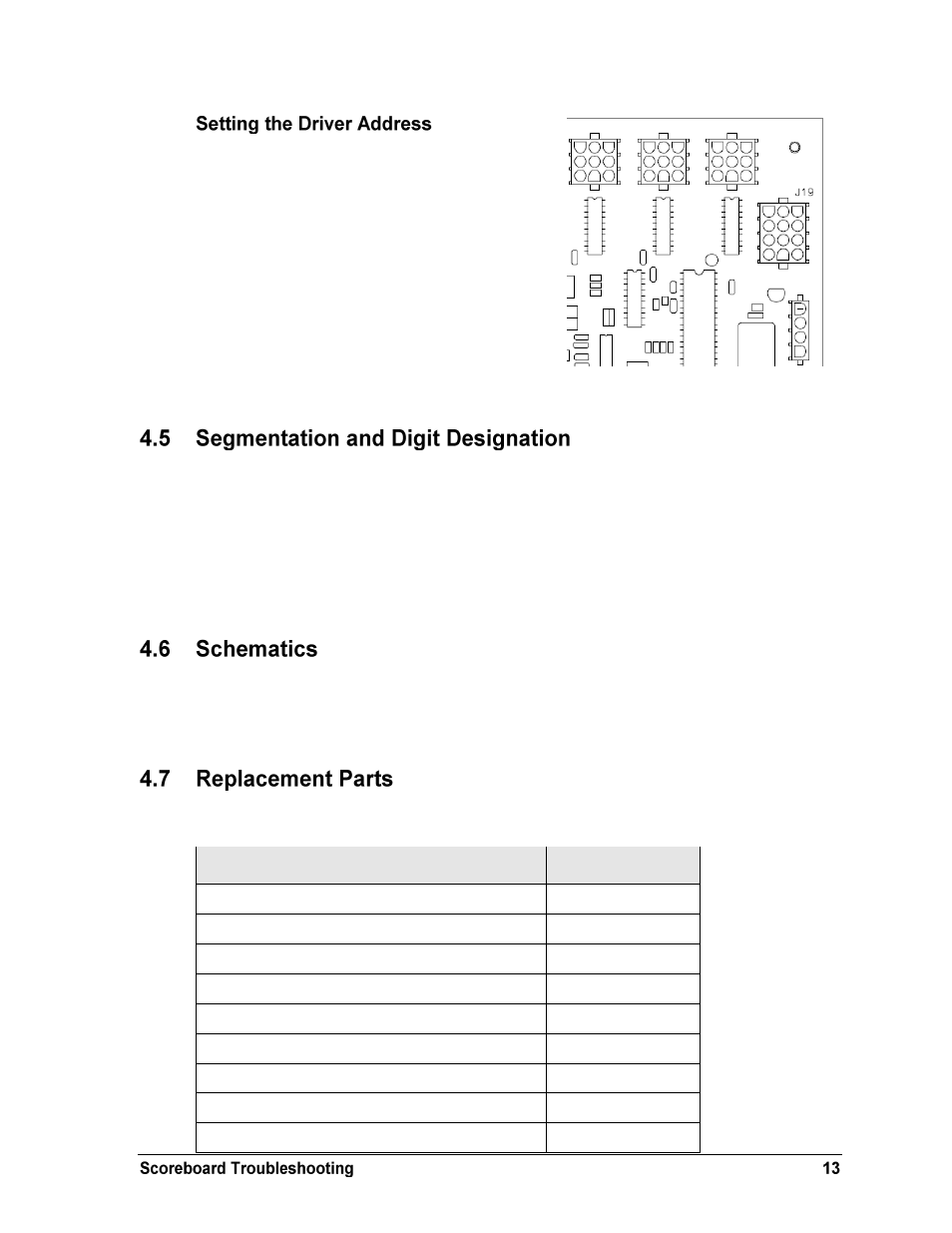
Since the same LED drivers can be used for many
scoreboard models, each driver must be set to
receive the correct signal input, or address, for the
model being used. This address is set with jumper
wires in a 12-pin plug which mates with jack J19
on the driver (Figure 5).
When setting the driver address, refer to Drawing
A-115078 in Appendix
A for a listing of the
wire/pin connections for driver addresses 1 – 128.
Note: All scoreboards in this manual should
be set to address “11”.
In each digit, certain LEDs always go on and off together. These groupings of LEDs are called
segments. Drawing A-38532 in Appendix A details which connector pin is wired to each
digit segment and the wiring color code used throughout the display.
The electrical and signal specification drawings in Appendix A also specify the driver
connectors controlling the digits. Numbers shown in hexagons in the upper half of each digit
indicate which connector is wired to that digit.
For advanced scoreboard troubleshooting and repair, it may be necessary to consult the
schematic drawings. Drawing A-258626 in Appendix A shows detailed power and signal
wiring diagrams of internal display components.
Refer to the following table for common Daktronics scoreboard replacement parts:
Description
Daktronics Part #
16 Column LED Driver II
0P-1150-0126
Digit, 5" red 7 segment LED
0P-1150-0200
Transformer, 120P/16S, 6.3 A
T-1066
Cable, 20' phone plug
W-1236
Cable, 50' phone plug
W-1237
Cable, 30' phone plug
W-1238
Cable, 10' phone plug
W-1340
Tripod Mount
HS-1306 & A-1580
Replacement T-bolt for Tripod Mount
HS-1315
Figure 5: Driver Address Jack J19