Replacing a digit, 3 led drivers, Led drivers – Daktronics FB-2006 Generation III Stackable LED Scoreboard User Manual
Page 32
26
Maintenance and Troubleshooting
Component location varies with each scoreboard model, but drivers and power and
signal components are typically mounted inside the scoreboard behind an access
panel or a digit.
Note: Disconnect power before servicing the display! Disconnect power, too,
when the display is not in use. Prolonged power-on may shorten the life of some
electronic components.
Replacing A Digit
Reference Drawings:
Digit Service, Stackable Scoreboards................... Drawing A-156994
Digit Assemblies; Gen III LED Digits..................... Drawing B-177679
The digit circuit board, the platform for the LEDs, is mounted to the back of the digit
panel. Refer to Drawings A-156994 and B-177679 for details. Do not attempt to
remove individual LEDs. In the case of a malfunctioning board, replace the entire
face panel.
To remove a scoreboard digit, follow these steps:
1. Open the face panel as described in the preceding section.
2. Disconnect the power/signal connector from the back of the digit. Release
the connector by squeezing together the locking tabs as you pull the
connector free.
3. The digits are secured to the inside of the panel with fixed machine screws,
spacers, and push nuts.
4. Remove the nuts and lift the digit off the standoff screws. (The push nuts
can be removed in several ways, but Daktronics recommends using a
9
/
32
"
nut driver.)
5. Position a new digit over the screws and tighten the nuts.
6. Reconnect the power/signal connector.
Note: This is a keyed connector. It will attach in one way only.
Do not attempt to force the connection!
7. Close and secure the digit panel and test the scoreboard.
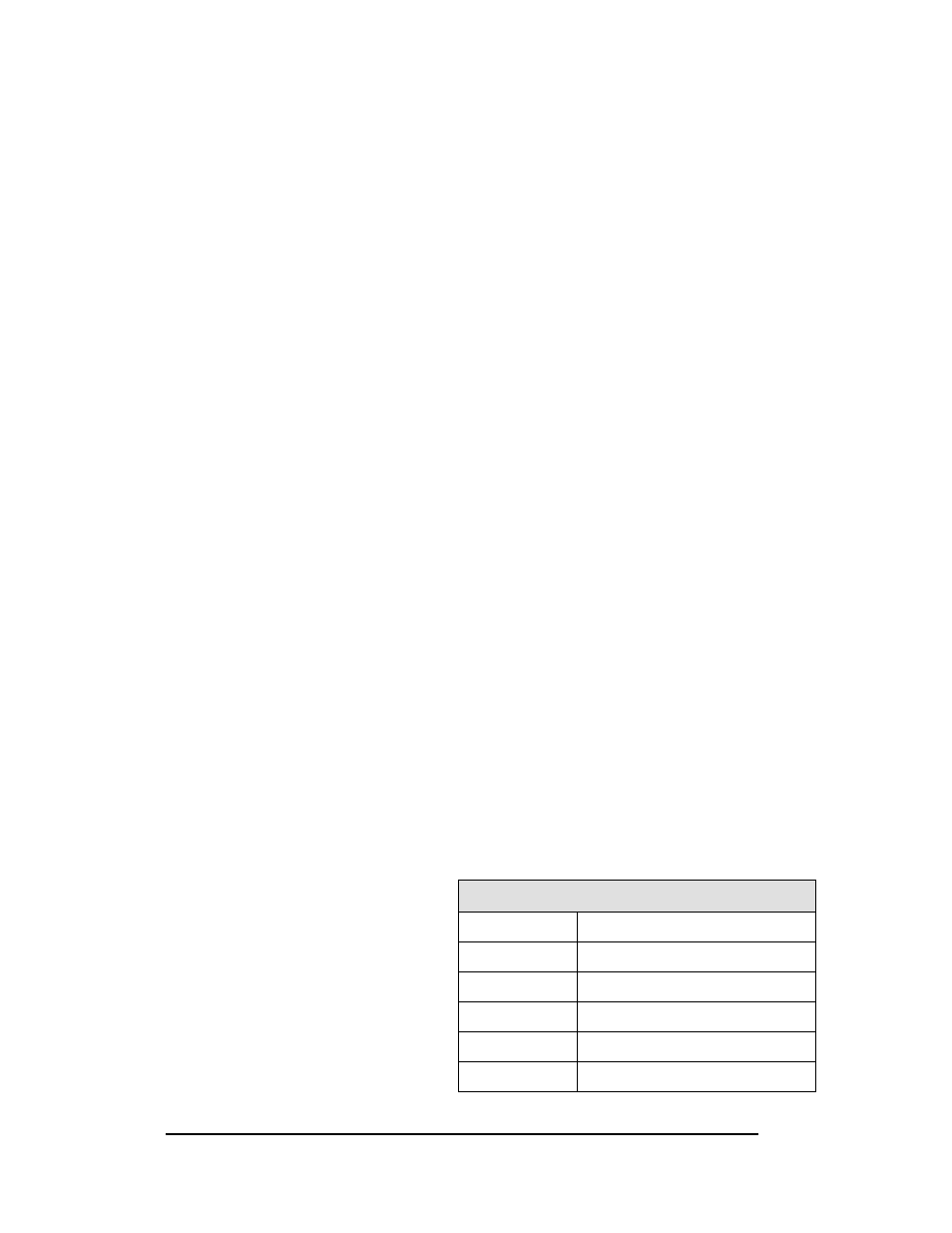
5.3 LED Drivers
In the scoreboard, the LED drivers
perform the task of switching
digits on and off. Refer to
Drawing A-178197. Each driver
has up to 19 connectors providing
power and signal inputs to the
circuit and outputs to the digits and
indicators. The connectors
function as shown in the table at
right.
16-Column LED Driver
Connector No.
Function
1
– 16
Output to digits and indicators
17
Power and signal input
18
Relay
19
Address
20
Protocol