2 power and signal connection, Power and signal connection – Daktronics FB-2006 Generation III Stackable LED Scoreboard User Manual
Page 27
Electrical Installation
21
4.2 Power and Signal Connection
Reference Drawings:
Schematic, Gen III Outdoor LED,
16 Column Driver ................................................... Drawing A-177931
Driver; Gen III LED, 16 Col Master .............................. Drawing A-178197
Route power and signal cables into the scoreboard from the rear. There are two
knockouts for conduit connection in the back. All power and signal wiring terminates
at the driver enclosure. Drawing A-178197 illustrates the 16-column driver used in
Daktronics outdoor LED scoreboards.
To gain access to the driver enclosure, open the access door or digit panel and
remove the cover from the enclosure. Refer to the component locations drawings for
the access location for your scoreboard.
Connect power and signal cables at the appropriate locations on the driver enclosure
panel, shown in Drawings A-178197 and
A-177931.
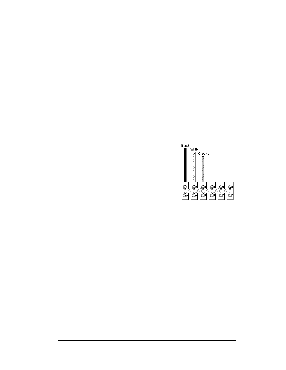
The conventional power termination panel has been
eliminated from Daktronics outdoor scoreboards;
the power feeder circuit connects directly to a
terminal block in the driver enclosure, as shown in
Figure 3. The terminal block is located in the lower
right corner of the enclosure. Connect the power
wires as shown in the illustration. Refer to the
driver engineering drawing and the schematics
listed at the beginning of this section for additional
wiring details. The schematics include a detailed
illustration of the power termination.
Note: Driver enclosures in some earlier Daktronics scoreboards included a 120
V power receptacle. There is no 120 V receptacle in Generation III displays. If you
want power to operate the control console at the scoreboard for troubleshooting,
Daktronics recommends that you have the installation electrician provide a 120 V
outlet close to the disconnect box specifically for this purpose.
Route signal cabling to the signal surge arrestor card in the upper left corner of the
driver enclosure. The connections are labeled to permit easy installation.
Figure 3: Power Terminal Block