Major assembly, Installation, Initial configuration – Comtech EF Data CMR-6000 Quick Start Guide User Manual
Page 2
MN-CMR6000-QSG Rev
1
Copyright © 2008 Comtech EF Data, 2114 West 7th Street, Tempe, Arizona 85281 USA. All rights reserved. Printed in the USA.
Major Assembly
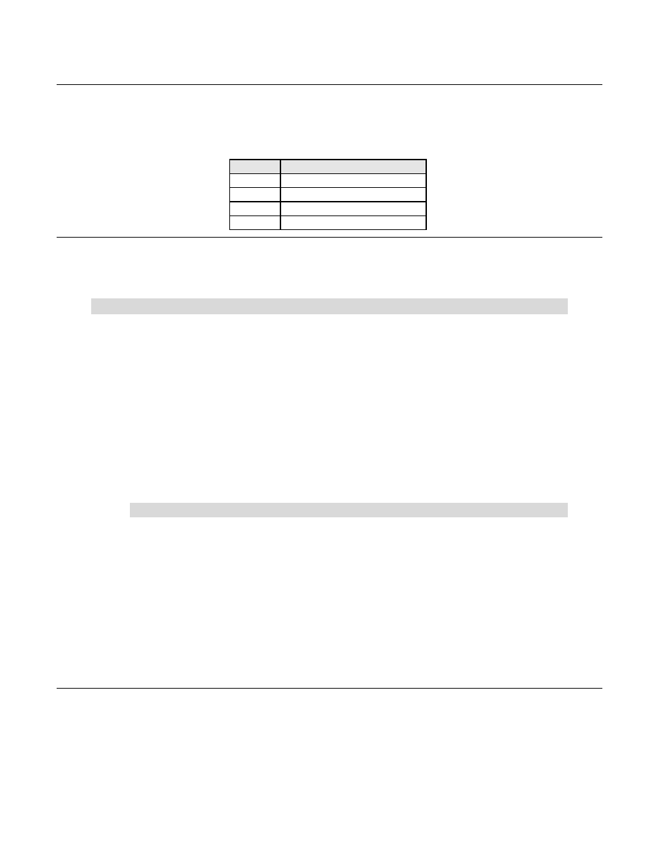
The Comtech EF Data Digicast Media Router CMR-6000 is available in a standalone configuration. The
following table lists the components provided with a standard configuration. In the event any listed item
is missing, please contact Comtech EF Data Customer Support.
Quantity
Description
1
CMR-6000 [CMR-6000]
1
IEC Power Cable
1
CA-TERMINAL Terminal Cable
1
Quick Start sheet
Installation
The CMR-6000 is designed for ease of installation and configuration. Once the unit has been removed
from the packing container, please follow these instructions:
Step Procedure
1
Place the unit on a flat surface with free airflow, where the LEDs can be clearly observed
and with unrestricted access to the rear panel of the unit.
2
Until the unit has been fully configured, the coaxial connection to the Low Noise Block
(LNB) should NOT be connected to the unit. If the unit will not be powering the LNB, it is
recommended that 'Polarity' (on the 'Tuner' configuration page) be set to 'Off'.
3
Connect the power cable to the back of the unit.
4
Connect an RJ-45 Ethernet cable (patch cord) to the port labeled ETHERNET and to an
Ethernet concentrator (hub) or switch.
5
Connect a terminal cable P/N CA-TERMINAL (supplied) to the port labeled TERM and to
a PC’s serial port (DB-9), to initially configure the CMR-6000.
6
Connect the AC power cord to a standard wall outlet and the unit.
7
Upon startup, the LEDs on the front panel may illuminate as follows:
Color
Label
Description
Green
/
Red
STATUS
Red indicates error status, green indicates status ok
Green
LOCK
Solid green indicates the tuner is locked
Green
E-LINK
LED illuminates if the Ethernet connection to the Hub/Switch
is operational
Green
REDUN
Redundancy indicator. Solid green unit is redundant online
and flashing green is redundant offline (backup)
Amber
ASI-TX
Solid when ASI is enabled
Amber
ASI-RX
Solid when ASI input is connected
Amber
E-ACT
Flashes when there is Ethernet activity
Solid when management connection (web or Telnet)
Amber
MGT
Initial Configuration
The initial configuration requires setting up the IP parameters via the terminal cable. Once the IP
parameters have been configured, the terminal cable can be removed. Store the terminal cable in a known
location, because it may be needed in the future. The front panel may also be used for initial configuration
of the IP parameters.