Cb 9 series – Code Blue CB 9-S SIGNATURE SHORT ENCLOSURE User Manual
Page 23
Code Blue
•
259 Hedcor Street
•
Holland, MI 49423 USA
•
800.205.7186
•
www.codeblue.com
GU-159-D
page 23 of 38
CB 9 Series
Administrator Guide
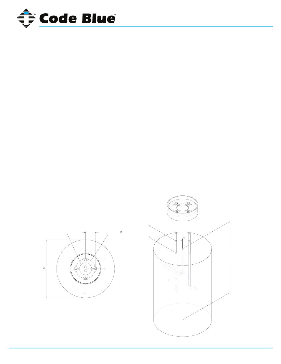
15 CB 9 Series Anchor Bolt Installation Instructions
1.0 FOUNDATION
1.1 Conduit – Electrical and telephone line conduit, with a maximum combined diameter of
four inches, should be run up through the center of the foundation hole. A minimum of four
inches and a maximum of six inches of conduit above the finished grade level is required. To
ensure proper grounding, a ½-inch x 8-foot copper rod should be inserted in the center of the
foundation and tied to the steel bollard.
NOTE: Follow all national and local codes governing this installation.
1.2 Pour the Foundation – The foundation should be at least 24 inches in diameter and to the
correct depth for the frost line in your area, with a minimum depth of at least three feet (follow
local building codes for foundations).
1.3 Set the Anchor Bolts in the Wet Foundation – Four 24-inch L-shaped anchor bolts and an
aligning template are supplied for anchoring the Code Blue unit. The bolts should be set into
the foundation so that six inches are left showing above the finished grade level. The anchor
bolts should be aligned, using the supplied template in such a way that the phone faceplate
on the unit will face in the desired direction.
2.0 WIRING
2.1 Pull power and phone line up through the conduits – A minimum of two feet of wire must be
available from the conduit for electrical and communications wiring.
TO BE DETERMINED
BY FROST LINE AND
LOCAL CODES
6.00
4.00
4.00
24.00
8.00
BOLT CIRCLE
FOR ANCHOR BOLTS
KEEP CONDUIT
CONTAINED WITHIN
4.00" DIAMETER
PHONE FACEPLATE DIRECTION
USE PROVIDED TEMPLATE TO LOCATE ANCHOR BOLTS