Terminator data unit – Codan Radio P25 Training Guide User Manual
Page 65
P25 RADIO SYSTEMS | TRAINING GUIDE
Chapter 4: Anatomy of the Common Air Interface Page 57
TERMINATOR DATA UNIT
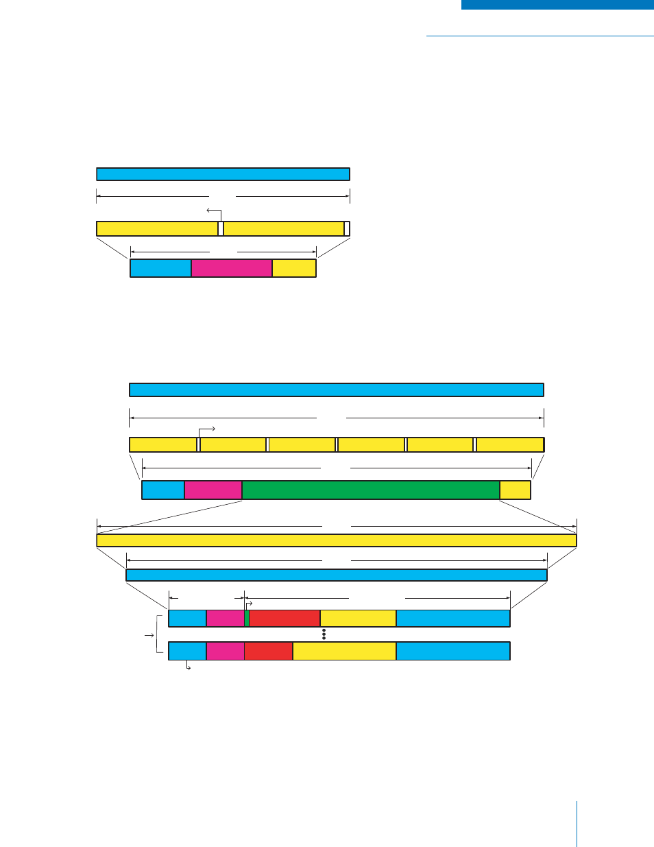
Voice messages may use one of two different Terminator Data Units. The simple Terminator Data
Unit is composed of the FS (48 bits), NID (64 bits), and Null bits (28 bits). A diagram of the simple
Terminator Data Unit is given in Figure 4-10.
Figure 4-10: Terminator Data Unit without Link Control Info
The Terminator Data Unit can also be sent with the Link Control Word embedded in it. A diagram of the
expanded Terminator Data Unit is given in Figure 4-11. The Link Control Word is the same as the Link
Control Word used in LDU1, except that it is error protected with a Golay code instead of the Hamming
code.
Figure 4-11: Terminator Data Unit with Link Control Info
When the voice message is fi nished, the transmitter continues the transmission, by encoding silence for
the voice, until the Logical Link Data Unit is completed. Once the Logical Link Data Unit is completed,
the transmitter then sends the Terminator Data Unit to signify the end of the message. The terminating
data unit may follow either LDU1 or LDU2.
TDU without Link Control Info (144 bits / 15 ms)
Status Symbol Each 2 bits
for Every 70 bits (2 X 2 = 4 bits)
144 bits
FS 48 bits
NID 64 bits
Null
28 bits
140 bits
TDU with Link Control Info (432 bits / 45 ms)
RS Code (24,12,13)
Extended. Golay Code (24,12,8)
144 bits
288 bits
FS 48 bits
NID 64 bits
LC Code Word 288 bits
Null
20 bits
420 bits
Status Symbol Each 2 bits for Every 70 Bits (6 X 2 = 12 bits)
432 bits
Link Control Format (LCF) to specify the word's information
content (this shows two examples only)
2 octets (16 bits)
7 octets (56 bits)
LCF Octet
$00
MFID
Reserved 15 bits
TGID 16 bits
Source ID 24 bits
Emergency bit (Flag)
LCF Octet
$03
MFID
Reserved 8
bits
Destination ID 24 bits
Source ID 24 bits
Two examples of
Link Control Info