Connecting multiple me-1s, Me-1 installation guide v1.0 3, Me-1 – Cloud Electronics ME-1 Installation User Manual
Page 3
ME-1 Installation Guide v1.0
3
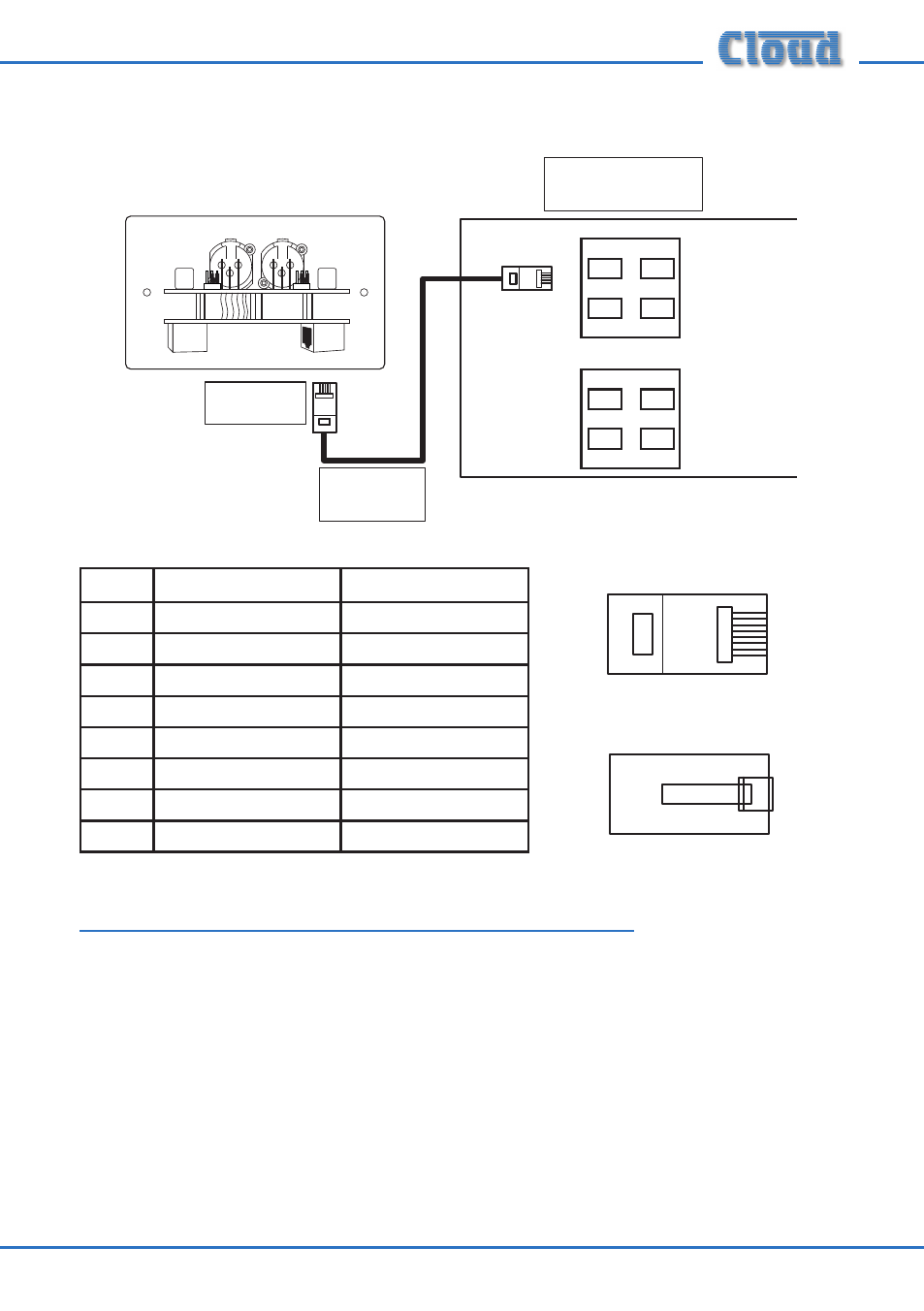
Connect to
Output socket
Screened
CAT-5 cable
Microphone Inputs
Extension Ports
DCM-1
1
2
3
4
1
2
3
4
Connect to an
unused Microphone Input
ME-1
OUTPUT
LINK
PIN
USE
CAT-5 CORE
1
Mic sum (cold)
White + Orange
2
Mic Sum (hot)
Orange
3
Sense
White + Green
4
DC +ve
Blue
5
0v
White + Blue
6
DC -ve
Green
7
n/u
White + Brown
8
n/u
Brown
Connecting Multiple ME-1s
Multiple ME-1s may be “daisy-chained” together to provide additional input points,
normally in the same zone. Signals applied to plates wired in this way will be summed
together to the DCM-1 Microphone Input to which the “last” ME-1 in the chain is
connected. An internal gating circuit on each plate automatically “disconnects” any
chained plates which are not in use, to minimise noise contribution. All microphones
plugged into ME-1s on such a chained system will be summed together into one mono
signal.
Multiple ME-1s may be daisy-chained together by connecting the LINK RJ45 socket on
the first ME-1 (that whose OUTPUT socket is connected directly to the DCM-1) to
the OUTPUT socket on the second ME-1, and so on, as shown on page 4.
1
8
1
8
1
8
1
8