Introduction - continued, Mounting - mechanical, Wiring – Cloud Electronics ME-1 Installation User Manual
Page 2
ME-1 Installation Guide v1.0
2
Introduction - continued
The two microphone channels are identical.
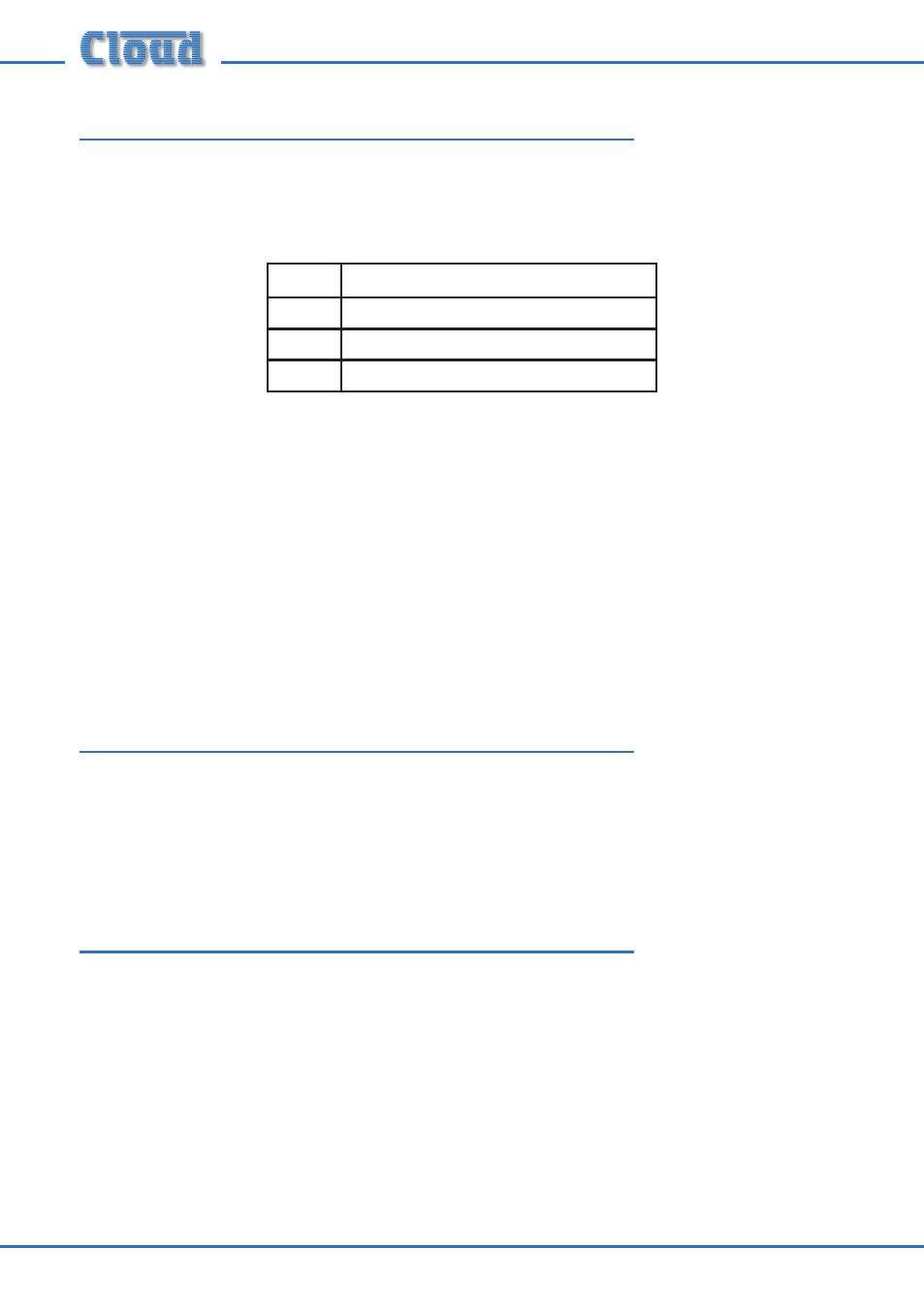
The mic input connector is a 3-pin latching female XLR, wired to the industry-standard
pinout:
PIN
FUNCTION
1
Ground
2
Signal ‘hot’ (+, phase)
3
Signal ‘cold’ (-, antiphase)
Phantom power (12v) can be activated by a rear jumper (see below), permitting the
use of either dynamic or condenser microphones. Between -85dB and +60dB of gain
adjustment is available with the faceplate control to suit most types of microphone;
when the plate is in use, mic volume is adjusted with this control alone. HF and LF EQ
adjustment is provided via two screwdriver-operated preset controls; these should
be adjusted using the microphone (and ideally, the speaker him/herself) for optimum
clarity.
See the DCM-1 Installation and User Guide, p33, for details of how an ME-1 input plate
is activated.
Mounting - mechanical
The Cloud ME-1 fits a standard dual-gang electrical back box. The back box used should
have a depth of at least 35mm (1.25”). Note that the ME-1 is made in various faceplate
sizes to suit standard electrical plate sizes in use in the UK, USA and Australia; ensure
you have the correct version for your territory.
Wiring
The ME-1’s OUTPUT connector should be connected to one of the DCM-1’s
MICROPHONE INPUTs with screened CAT-5 cable and shielded RJ45 plugs.
Note that because the cables carry low-level audio, only screened CAT-5 should be
used, the foil screen of the cable being bonded to the metal screening can of the plugs.
If an ME-1 is being mounted in close proximity to the DCM-1, it may be possible to
use ready-made screened CAT-5 “patch” cables of an appropriate length. Otherwise,
shielded RJ45 plugs should be crimped onto the installed screened CAT-5 cable using
the pinout shown below.