2 schematic diagram, Cx242: i – Cloud Electronics CX242 User Manual
Page 3
CX242: I
NSTALLATION AND OPERATION MANUAL
2
1 Safety
Notes
• Do not expose the unit to water or moisture
• Do not expose the unit to naked flames.
• Do not block or restrict any air vent
• Do not operate the unit in ambient temperatures above 35
o
C
• Do not perform any internal adjustments unless you are qualified to do so and fully
understand the hazards associated with mains operated equipment.
• The unit has no user serviceable parts. Refer any servicing to qualified service
personnel.
• If the moulded plug is cut off the lead for any reason, the discarded plug is a
potential hazard and should be disposed of in a responsible manner.
For more detailed information refer to the rear of the manual.
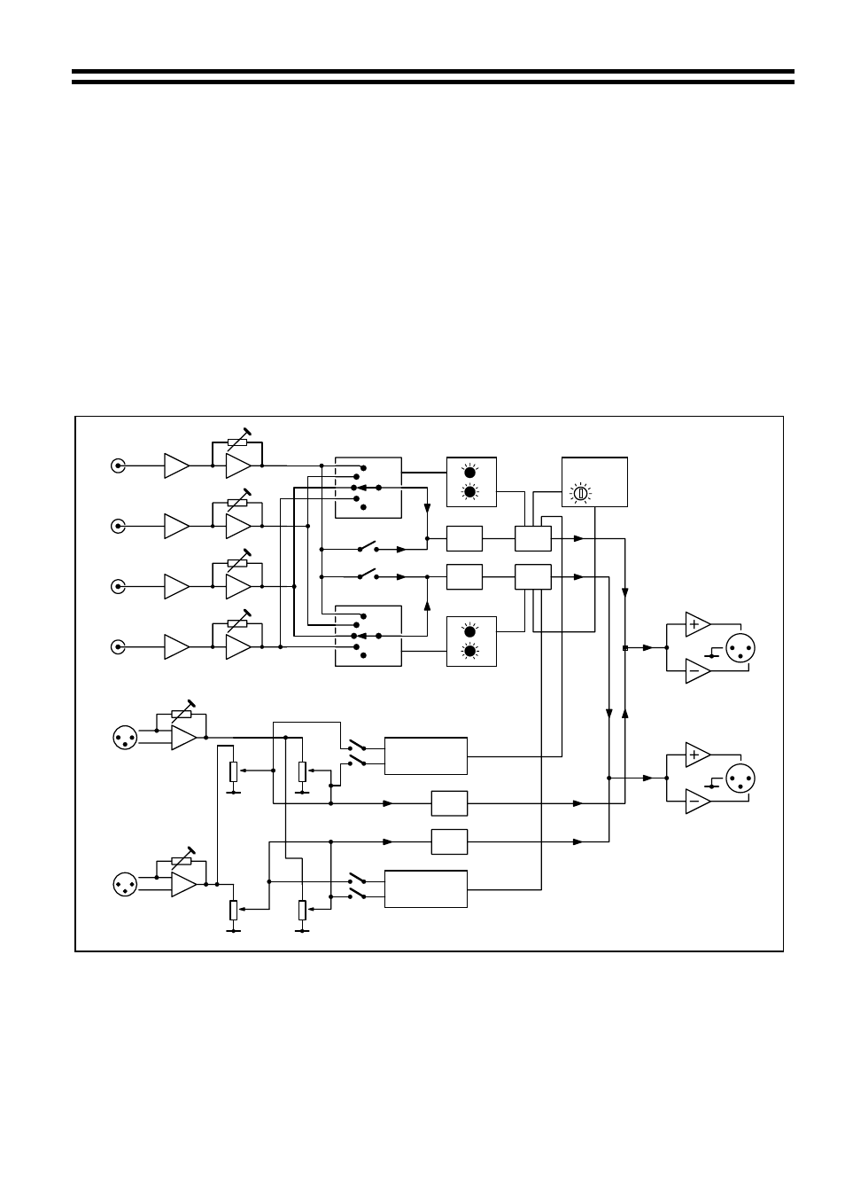
2 Schematic
Diagram
DC CONTROLLED
SOURCE SELECT
REMOTE OR LOCAL
SOURCE SELECT + LEVEL
FIRE ALARM
MUSIC MUTE
LEVEL
EQ
VCA
EQ
VCA
LINE 4 PRIORITY
DC CONTROLLED
SOURCE SELECT
REMOTE OR LOCAL
SOURCE SELECT + LEVEL
EQ
EQ
ZONE 1
MICROPHONE
AUTO PRIORITY
ZONE 2
MICROPHONE
AUTO PRIORITY
MIC 2
ZONE 2
MIC 1
ZONE 2
MIC 1
ZONE 1
MIC 2
ZONE 1
GAIN
GAIN
MIC 1
MIC 2
LINE 4
LINE 3
LINE2
LINE 1
GAIN
GAIN
GAIN
ZONE 1
OUTPUT
ZONE 2
OUTPUT
GAIN
For clarity only one channel shown
15/07/02 V4