Appendix, Application example, Z4-8 – Cloud Electronics Z4MK3 User Manual
Page 21: Installation and user guide 21, The z4, And z8
Z4-8
MK3
Installation and User Guide
21
APPENDIX
Application example
The Z4
MK3
and Z8
MK3
will find application in many types of premises, including shops, bars, hotels, schools, conference centres,
offices, etc.
A typical example using most of the Zone Mixer’s facilities is given below.
ZONE 5
ZONE 3
ZONE 2
ZONE 6
ZONE 8
ZONE 4
ZONE 7
ZONE 1
ZONE 5
ZONE 3
ZONE 2
ZONE 6
ZONE 8
ZONE 4
ZONE 7
ZONE 1
ZONE 5
ZONE 3
ZONE 2
ZONE 6
ZONE 8
ZONE 4
ZONE 7
ZONE 1
OUTPUTS
REMOTE SOURCE + LEVEL PORT
S
FACILTY PORT
S
INPUT 1
INPUT 6
INPUT 4
INPUT 2
INPUT 3
INPUT 5
MIC 1
MIC 2
PAGING MIC
PAGING ACCESS
CD PLAYER
PC
RADIO
TUNER
FREEVIEW
RECIEVER
AREA 1
AREA 2
AREA 3
POWER
AMPLIFIERS
OTHER
AREAS
PM PAGING
MICROPHONE
RSL-6
LM-2
RL-1
LOCAL
MICS
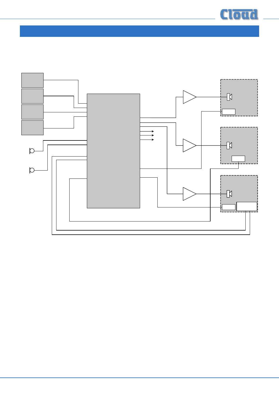
The diagram depicts a system where four possible music (or other audio) sources are made available to three or more zones
(areas). Only three are shown for clarity. Points to note:
•
Area 1 and Area 3 have remote control plates installed: an RSL-6 Series (music level and source) in Area 1 and an RL-1
Series (music level only) in Area 3. These are wired to the REMOTE SOURCE+LEVEL Ports for their respective zone
outputs.
•
Area 2 includes an LM-2 mic/line input module wired to Zone 2’s FACILITY PORT This would allow both a microphone
and a portable stereo music source to be connected in that area. The LM-2 also provides music source and level control;
note that the LM-2 does not require a second connection to the REMOTE SOURCE+LEVEL Port to enable this.
•
Area 3 has a Cloud PM paging microphone, which would be used to originate voice messages to any of the areas. The
paging level to Area 3 (if required) would be adjusted on installation to be at a level that does not cause feedback.