15 equalisation module installation, 16 field servicing, 17 general specifications – Cloud Electronics CXA850 User Manual
Page 9
CX-A850: Installation and Operation Manual
7
08-03-05 V4
15
Equalisation Module Installation
1. Turn the power off and remove the mains lead.
2. Remove the top panel from the unit.
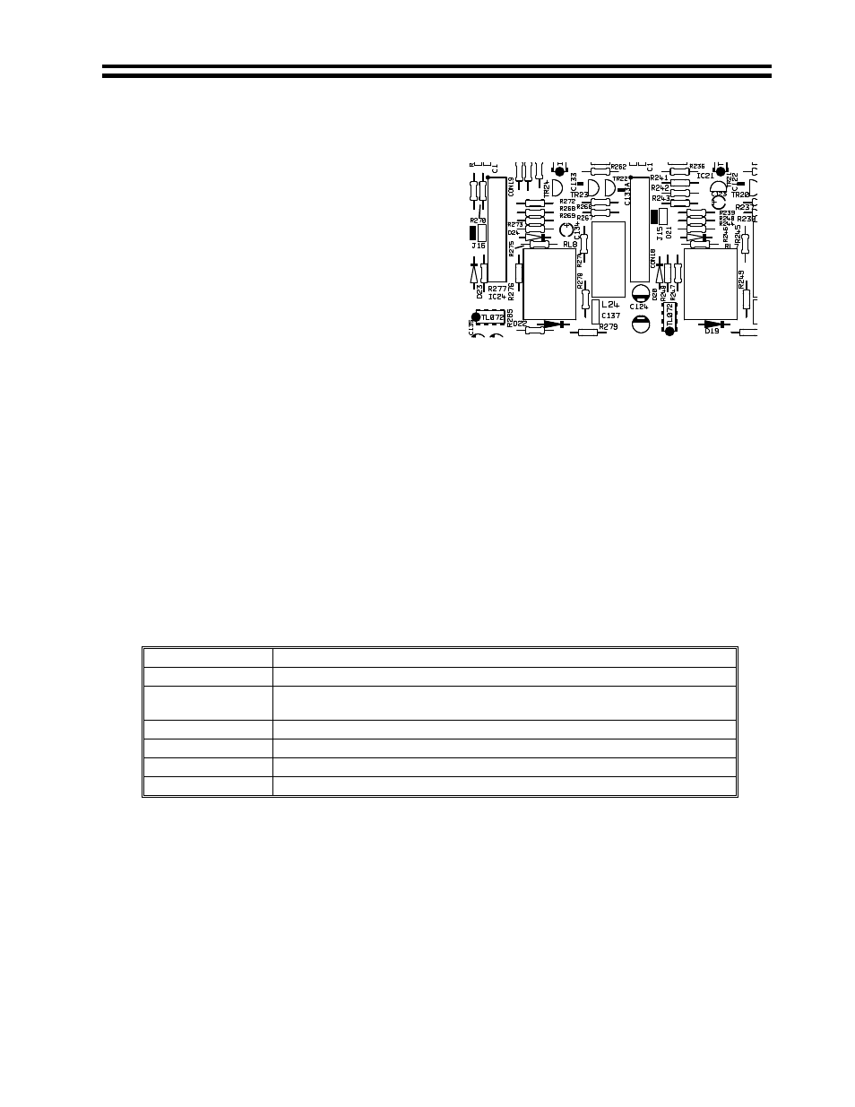
Channel 7&8 PCB Connector Locations
3. Select the required PCB connector (see
Fig 12 adjacent) that you wish to install
the equalisation module to and remove
the jumper from it.
CON12 & J9 = Channel 1
CON13 & J10 = Channel 2
CON14 & J11 = Channel 3
CON15 & J12 = Channel 4
CON16 & J13 = Channel 5
CON17 & J14 = Channel 6
CON18 & J15 = Channel 7
CON19 & J16 = Channel 8
4. Configure the relevant 65Hz filter to ‘ON’ and connect a CXL-40T 100V line transformer
(see section 7)
5. Fit the EQ card to the connector such that the EQ card is perpendicular to the main board
6. Push down on the EQ card until it locates with a click.
7. Replace the top panel.
NOTE: Before installing active modules, check section 10 for details of the power supply on
the CX-A850. Each channel of the CX-A850 can have both a VCA-5 module and a speaker
EQ card installed at the same time.
16
Field Servicing
The CX-A850 is ruggedly built and uses proven reliable circuitry. It requires no more than the
occasional removal of any dust that may have built up inside the unit because of the forced
cooling.
17
General Specifications
Inputs
Balanced via 3-pin plug-in screw terminal type connectors
Outputs
2-pin plug-in screw terminal type connectors for flexible cables up to 2.5mm²
Protection
VI limiting, DC offset, Thermal, Switch-on Delay & Dynamic Clipping
Protection
Status Indicators
LED indicators on each channel for Signal, Peak &Protect
Cooling
Force cooled using variable speed DC fan
Dimensions
482.6mm x 88.0mm (2U) x 300.0mm deep (+ connectors)
Weight
8.8kgs
Fig 12