Zone 1 output, Zone 2 output, Utility output – Cloud Electronics 36-50 - CXL-3120 User Manual
Page 4
CXL-3120 Installation Instructions v1.0
4
OF
F
ON
OFF ON
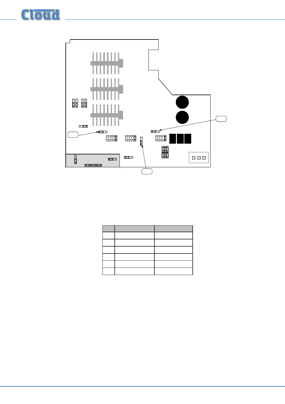
J5
SW FR
SW FR
OF
F
ON
J8
OFF ON
J9
OF
F ON
OF
F ON
6S 3S
NOT TO SCALE – ONLY PRIMARY
COMPONENTS SHOWN
36-50 Jumper locations for Step 5.
6. Fit the two hex spacers supplied in the kit into the holes vacated in Step 2, using the same screws, nuts and washers.
7. Replace the 36-50 top cover, and reinstall in the rack (if necessary); reconnect all inputs and outputs.
8. Connect the 70/100 V-line loudspeaker system using the supplied mating connector (see section: “Output wiring”) according to
the table below:
PANEL MARKING
CONNECT TO:
1
Z1+
Zone 1 output ‘+‘
2
Z1-
Zone 1 output ‘-‘
3
Z2+
Zone 2 output ‘+‘
4
Z2-
Zone 2 output ‘-‘
5
UT+
Utility Output ‘+‘
6
UT-
Utility Output ‘-‘
9. Fit the blanking plate from Step 2 onto the hex spacers (Step 6) over the connector, with the printed warnings outwards.
10. The 36-50 may now be reconnected to the AC mains and re-powered.