Block diagram, Front panel descriptions, Block diagram example system signal path – Cloud Electronics CX335 User Manual
Page 6: See “signal path considerations” on page 8), C x 3 3 5
CX335 User Manual v1.0
6
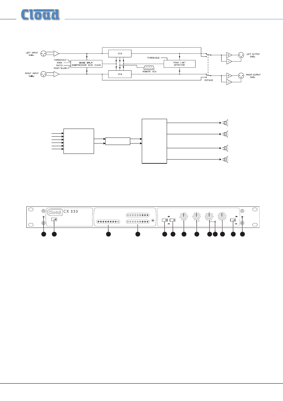
Block Diagram
Example System Signal Path
(see “Signal path considerations” on page 8)
Mixer or Zoner
Audio Sources
CX335
Loudspeaker Systems
Multi-Channel
Amplifier.
Front panel descriptions
Split Band Compressor-Limiter
C X 3 3 5
Power
GAIN REDUCTION
OUTPUT DISPLAY
30
-20
20
-16
15
-12
10
-8
6
-4
4
0dB
2
+4
1
+8
0dB
+12
KNEE
THRESHOLD
RATIO
PEAK
GAIN
BYPASS
4
4
0
3
10
- +
8
8
NORMAL
BYPASS
12
12
dB
L
R
LIMIT
dBu
6
15
20
0
26
-
NORMAL
SOFT
SLOW
HARD
3
-2
-4
6
2
5
10
20
1.5
1.2
:1
-10
-15
-20
+10
5
0
dBu
ENVELOPE
2
3
4
6
5
5
7
10
11
1
12
12
8
1. Power switch with integral LED
2. THRESHOLD – rotary control setting the signal level above which the compressor-limiter applies gain reduction.
3. RATIO – rotary control setting the degree of compression applied to signals above the threshold.
4. PEAK – rotary control setting the signal level at which the (independent) peak limiter operates.
5. LIMIT – red LED, illuminates when the peak limiter is active.
6. GAIN – adjust to match the output level to the input level on normal programme material when the CX335 is active.
7. ENVELOPE – push-button switch: Out = ‘Normal’; In = “Slow”. Select to obtain the best audible results for the type of
programme material in use.
8. KNEE – push-button switch: Out = “Hard”; In = “Soft”. Select to obtain the best audible results for the type of programme
material in use.
9. BYPASS – push-button switch; press to bypass all internal dynamics processing.
10. OUTPUT DISPLAY – two 9-segment LED bargraph meters showing the level of the L and R outputs in 4 dB steps from
-20 dB to +12 dB. The 0 dB LED is yellow, with higher and lower levels being indicated by red and green LEDs respectively.
0 dB is equivalent to an output level of 0 dBu (0.775 V
rms
).
11. GAIN REDUCTION – 9-segment LED bargraph meter indicating the degree of gain reduction being applied. The ‘0 dB’
LED is coloured green, and will remain illuminated even when there is no signal (thereby indicating that no gain reduction
is being applied).
12. 2 x M3 fixing holes for security cover